Piezoelectric / ultrasound transducer analysis
Performed calculations
If you have materials parameters and geometry of the piezo transducer, with the consent of Engineering Solutions, it is possible to order piezoelectric transducer parameter calculation. We can perform the following types of work:
Harmonic analysis
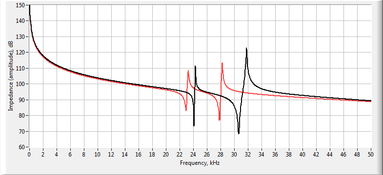
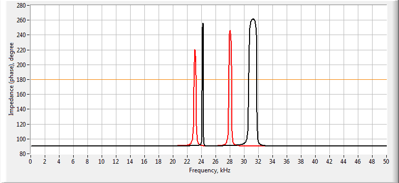
- calculation of the amplitude-frequency characteristic (AFC) and phase-frequency characteristic (PFC) of the conductivity and the impedance of the transducer / piezoelectric element;
- calculation of AFC and PFC of the sensitivity of the transducer;
- calculation of AFC and PFC of average displacement of the radiating surface of the transducer;
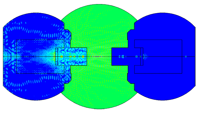
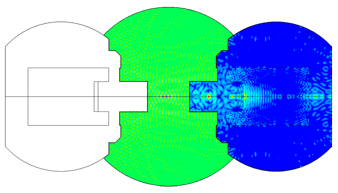
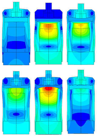
- determination of oscillation modes of the transducer.
-
![Piezoelectric transducer impedance AFC comparison Piezoelectric transducer impedance AFC comparison]()
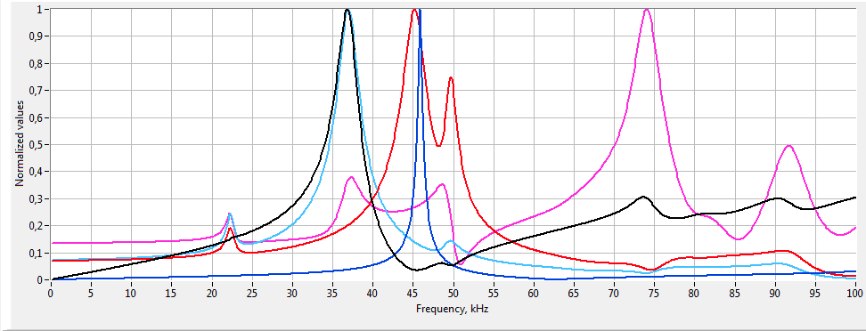
Example of comparison of the impedance amplitude-frequency characteristics of two different variants of the piezoelectric transducer models -
![Piezoelectric transducer impedance PFC comparison Piezoelectric transducer impedance PFC comparison]()
Example of comparison of the impedance phase-frequency characteristics of two different variants of the piezoelectric transducer models
Transient analysis
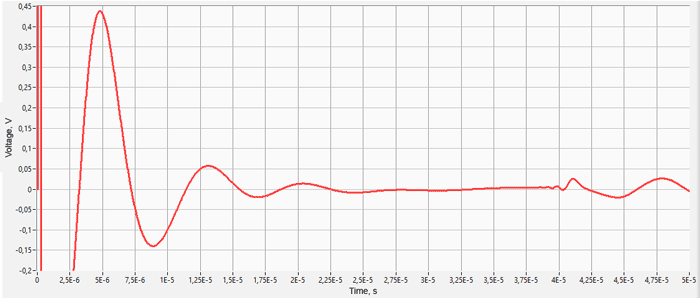
- calculation of voltage oscillograms on a piezoelectric element;
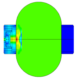
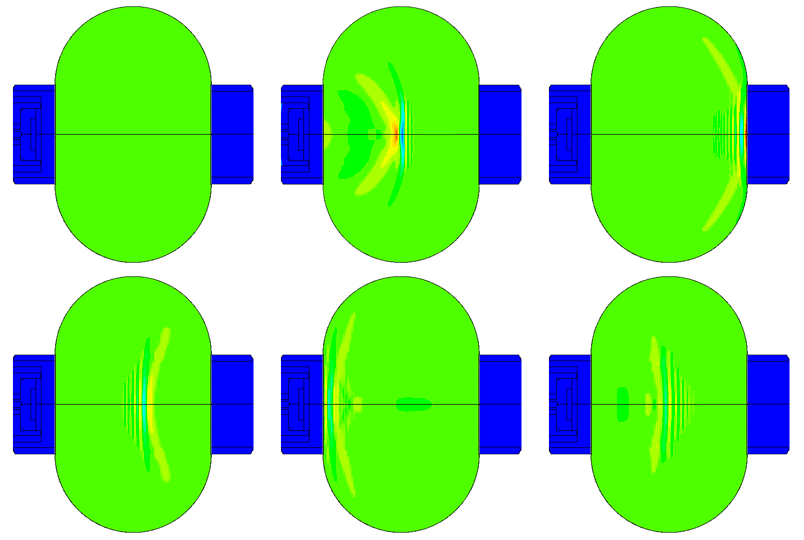
- calculation of displacements of the radiating surface
We also have a database of materials consisting of more than 100 components, including metals, polymers, composites, piezoceramic materials, etc.
Finite element equations for piezoelectric analysis
Allik and Hughes developed the finite element method for a piezoelectric material in 1970 [1]. For finite element analysis, ANSYS is using next form of the equation: [4]

-
- where {U} is an element structural displacement vector,
- {V} is a vector of nodal potential,
- [KUU] is an element structural stiffness matrix,
- [KVV] is an element dielectric permittivity coefficient matrix,
- [KUV] is piezoelectric coupling matrix,
-
- [CUU] is an element structural damping matrix,
- [CVV] is an element dielectric dissipation matrix,
- [MUU] is an element mass matrix,
- {F} is a vector of nodal and surface forces,
- {Q} is negative electric charge vector.
here [3]
-
- where c is structural stiffness, N/m2,
- ε is dielectric permittivity, F/m, [2]
- e is piezoelectric stress coefficient, C/m2,
- ρ is the density, kg/m3,
- σ is electrical conductivity, S/m,
- tanδ is electrical loss tangent,
- ω is angular frequency, rad/s
- Ω is the volume, m3,
-
- [KV] element electrical conductivity coefficient matrix,
- [σeff] is "effective" conductivity matrix,
- [NU] is element shape functions,
- [BU] is strain-displacement matrix,
- [BV] is the electric potential-electric field intensity matrix
The displacement field {U} and the electric potential {V} over the element can be defined in terms of the nodal displacements {Ui} and the nodal electric potentials {Vi} using corresponding shape functions defined as [NU] and [NV]:
The strain vector {S} and the electric field {E} are related to the displacement field {U} and the electric potential {V} using equations, respectively:


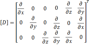
Here, [D] is the derivation operator defined as:
- Henno Allik, Thomas J. R. Hughes. Finite element method for piezoelectric vibration.- Groton, Connecticut, USA.: General Dynamics, Electric Boat Division, 1970
- Florence Rosenblatt-Weinberg. Modelling and optimisation of Electro-Active Polymer (EAP) devices.- London.: Imperial College of Science, Technology and Medicine, 2013
- Vinh-Tan Nguyen, Pankaj Kumar and Jason Yu Chuan Leong. Finite Element Modellingand Simulations of Piezoelectric Actuators Responses with Uncertainty Quantification.- Singapore.: Institute of High Performance Computing, 2018
- ANSYS Help. Theory reference. Piezoelectrics.
References
Different equations and matrix notation of IEEE and ANSYS
In linear piezoelectricity the equations of linear elasticity are coupled to the charge equation of electrostatics by means of piezoelectric constants (IEEE Standard on Piezoelectricity):
-
ANSYS equations
(stress-charge form)![]()
- where {T} is 6x1 stress vector (component order x, y, z, xy, yz, xz), N/m2
- {S} is 6x1 strain vector (component order x, y, z, xy, yz, xz), m/m
- {D} is 3x1 electric displacement vector (component order x, y, z), C/m2
- {E} is 3x1 electric field vector (component order x, y, z), V/m (C/N)
- [cE] is stiffness matrix evaluated at constant electric field, N/m2
- [e] is 6x3 piezoelectric matrix relating stress and electric field, C/m2 or N/Vm
- [e]T is transpose of [e]
- [εS] is dielectric matrix evaluated at constant strain, F/m
-
Piezoceramic manufacturer equations
(strain-charge form)![]()
- where {T} is 6x1 stress vector (component order x, y, z, yz, xz, xy), N/m2
- {S} is 6x1 strain vector (component order x, y, z, yz, xz, xy), m/m
- {D} is 3x1 electric displacement vector (component order x, y, z), C/m2
- {E} is 3x1 electric field vector (component order x, y, z), V/m (C/N)
- [sE] is compliance matrix evaluated at constant electric field, m2/N
- [d] is 6x3 piezoelectric matrix relating strain and electric field, C/N
- [d]T is transpose of [d]
- [εT] is dielectric matrix evaluated at constant stress, F/m
IEEE and ANSYS are using different matrix notation.
Piezoelectric transducer modeling
- Modeling of physical processes allows to calculate the characteristics of the sensor and its output parameters with high accuracy (error not more than 5%), such as:
- amplitude of oscillation (displacement);
- resonant frequencies;
- voltage on the piezo element, etc.
The developer can be more flexible at the conceptual design stage. Thus, prototypes creating and experimental tests conducting required only after calculating the optimal design of the sensor. This makes it possible to significantly reduce costs during the R&D phase and anticipate in advance the pitfalls.
Piezoelectric element FEA
The most difficult in the calculation of ultrasonic piezoelectric sensors is the simulation of the piezoelectric element. For a correct calculation of the piezoelectric element, it is required to know a large number of piezoceramic parameters. The graph (Fig. 1) shows the AFC of the piezoelectric element taken experimentally with help of impedance analyzer and calculated AFC of the piezoelectric element. The frequency error is 2.3% (at the first resonance) and 0.34% (at the second resonance).
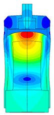
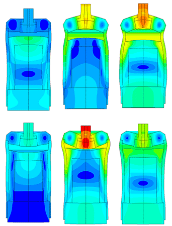
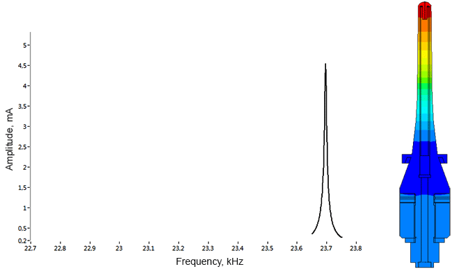
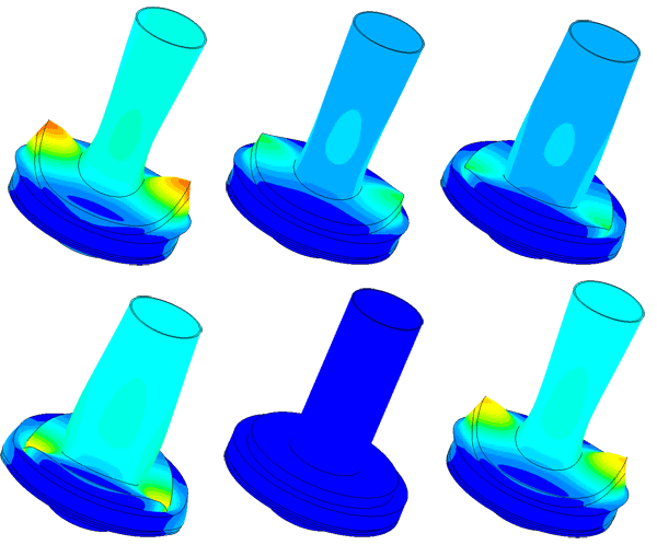
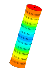
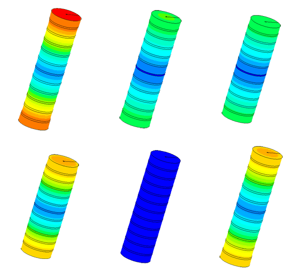
Scale of oscillations 200000: 1
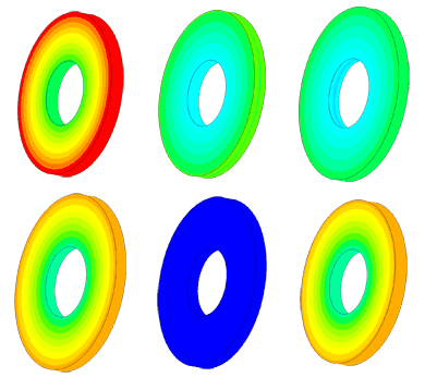

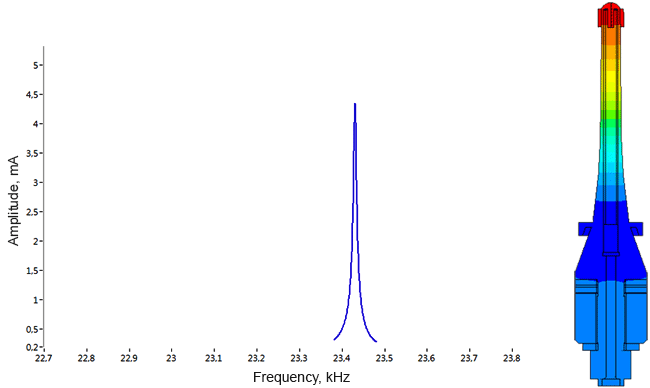
Scale of oscillations 10000:1
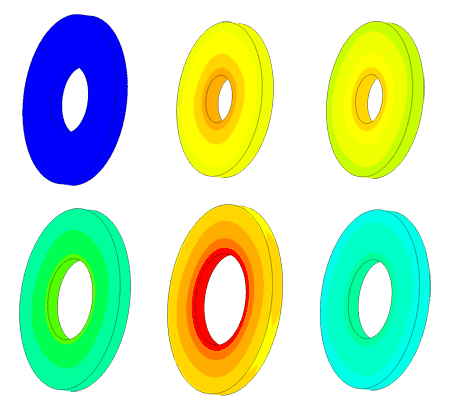
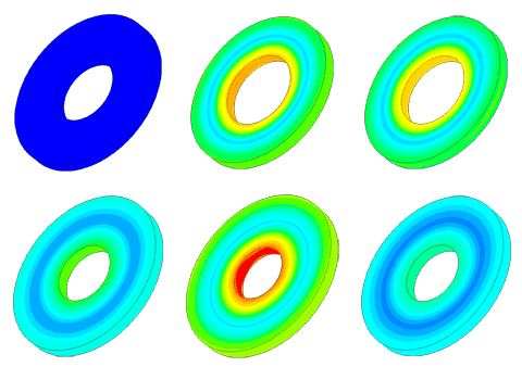
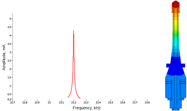
Scale of oscillations 10000:1
Portfolio
Ice sensor


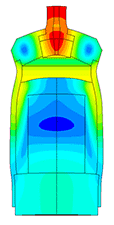
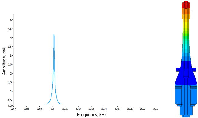
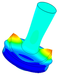
Scale of oscillations 10000:1
- Task:
- calculation of resonance frequency;
- determination of the frequency dependence on the amount of ice;
- calculation of spurious oscillations at the attachment point;
- determining the sensor sensitivity area.
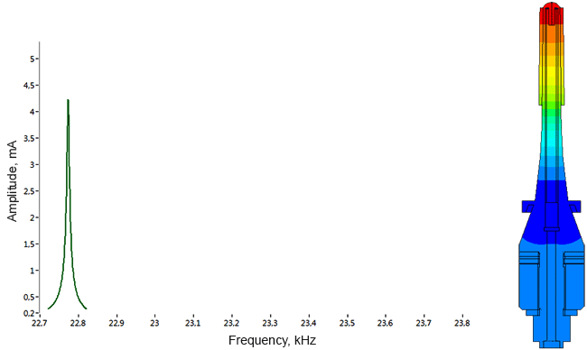
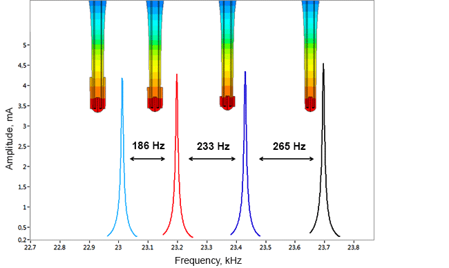
Densimeter
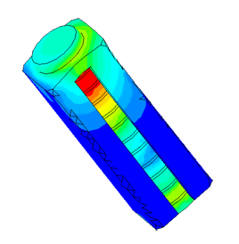
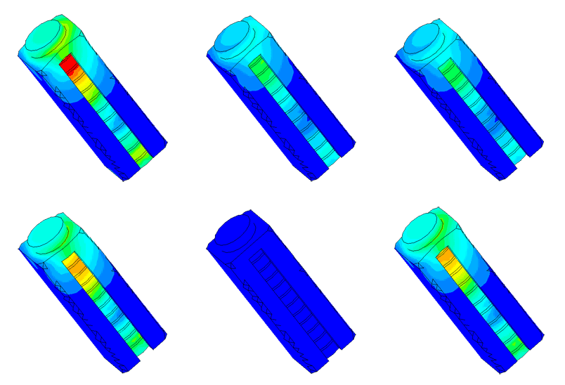
Determination of parasitic oscillations in a density meter.
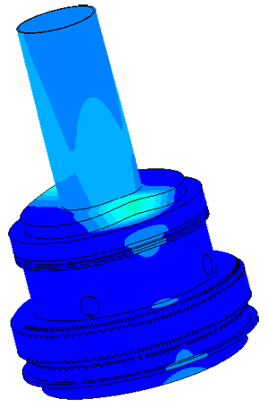
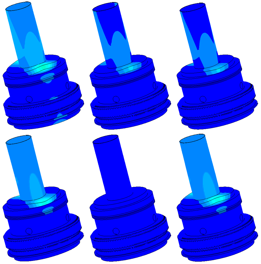
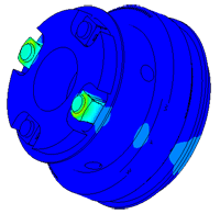
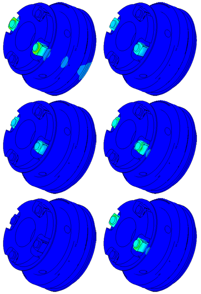
Model of a piezo package used in a density meter
Dispergator
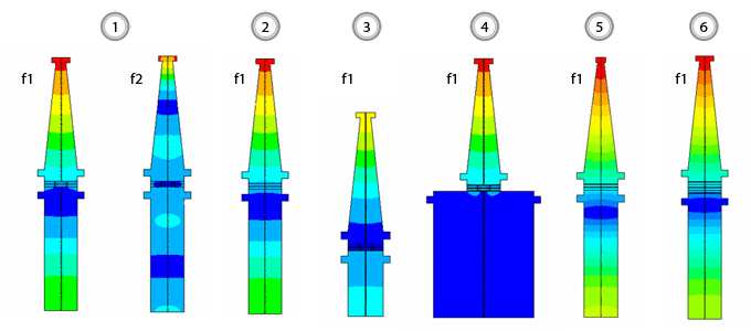
| № | Version | Frequency of the first resonance f1, Гц | Frequency of the second resonanceа f2, Гц | Mechanical amplitude of tip oscillations | |
| at f1, µm | at f2, µm | ||||
| 1 | initial | 18971 | 45295 | 36,29 | 24,55 |
| 2 | with a whole piezoelectric element | 19318 | 46189 | 42,46 | 28,08 |
| 3 | with reduced length of mass | 24697 | 40213 | 38,37 | 36,65 |
| 4 | with increased mass radius | 19226 | 39691 | 35,25 | 32,11 |
| 5 | with a modified horn | 20194 | 48475 | 40,33 | 37,03 |
| 6 | with 4 whole piezo elements | 18126 | 43230 | 46,85 | 33,94 |
Flowmeter
