Stepper motor
The predecessor of the stepper motor is the servo motor.
Stepper (pulse) motors directly (without a feedback sensor) convert the control signal in the form of pulses sequence into a fixed angle of the shaft rotation or linear movement of the mechanism that proportional to the number of pulses. This circumstance simplifies the drive system and replaces the closed-loop servo drive (servo) system with an open-loop one, which has such advantages as reducing the cost of the device (fewer elements) and increased accuracy due to the fixation of the stepper motor rotor at the absence of signal pulses.
The disadvantage of a drive with a stepper motor is also obvious: if a pulse fails, further tracking occurs with an error in the angle proportional to the number of missed pulses [2].
Therefore, in tasks where high performance (accuracy, speed) is required, servo motors are used. In other cases, due to the lower cost, simple control, and good accuracy, stepper motors are usually used.
The construction of stepper motor
A stepper motor, like any rotating electric motor, consists of a rotor and a stator. The stator is the stationary part, the rotor is the rotating part.

Stepper motors are reliable and inexpensive because the rotor has no slip rings and no commutator. The rotor has either salient poles or fine teeth. The reluctance stepper motor has a rotor made of soft magnetic material with salient poles. A permanent magnet stepper motor has a permanent magnet rotor. The hybrid stepper motor has a composite rotor including teeth (pole tips) made of soft magnetic material and permanent magnets. It is possible to determine whether the rotor has permanent magnets or not by rotating a de-energized motor, if there is a holding torque and/or pulsation during rotation, then the rotor is made on permanent magnets.
The stator of a stepper motor has a core with salient (protruding) poles, which are usually made of laminated stamped electrical steel sheets to reduce eddy currents and reduce heat build-up. The stator of a stepper motor usually has two to five phases.
Characteristics
Since the stepper motor is not designed for continuous rotation, power is not indicated in its parameters. A stepper motor is a low-power motor compared to other electric motors.
One of the defining parameters of a stepper motor is the rotor pitch (step), that is, the angle of rotor rotation corresponding to one pulse. The stepper motor makes one step per unit of time at the moment the control pulses change. The step size depends on the design of the motor: the number of windings, poles, and teeth. Depending on the design of the motor, the step size can vary in the range from 90 to 0.75 degrees. With the help of the control system, you can still achieve a step reduction in half using the appropriate control method.
Types of stepper motors
- According to the rotor design, there are three types of stepper motors::
- reluctance;
- with permanent magnets;
- hybrid.
Variable Reluctance Stepper Motor
A variable reluctance stepper motor is a synchronous reluctance motor. The stator of a reluctance stepper motor usually has six salient poles and three phases (two poles per phase), the rotor has four salient poles, with this design of the motor, the step is 30 degrees. Unlike other stepper motors, a switched-off variable reluctance stepper motor does not have a holding (braking) torque when the shaft rotates.

(step 30°)

(step 15°)
Below are the oscillograms of control for a three-phase stepper motor.


The control waveforms for a four-phase stepper motor are shown in the figure below. Sequential switching of the stator phases creates a rotating magnetic field followed by the rotor. However, due to the fact that the rotor has fewer poles than the stator, the rotor turns in one step at an angle less than the stator angle. For a reluctance motor, the step angle is:
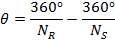 ,
,
- where NR is the number of rotor poles;
- NS is the number of stator poles.

To change the direction of rotor rotation (reverse) of a reluctance stepper motor, it is necessary to change the switching circuit of the stator windings, since the change in the pulse polarity does not change the direction of the forces acting on the unexcited rotor [2].
Variable reluctance stepper motors are used only when not very large torque and a sufficiently large step of the rotation angle are required. Such motors are now rarely used.
- Distinctive features::
- rotor made of soft magnetic material with salient poles;
- cheapest and least complex stepper motor;
- there is no detent torque in a de-energized state;
- large step angle.
Permanent Magnet Stepper Motor
A permanent magnet stepper motor has a permanent magnet rotor. The stator usually has two phases.
Compared to variable reluctance ones, stepper motors with an active rotor create large torques, ensure the rotor is fixed when the control signal is removed. The disadvantage of motors with an active rotor is a large angular step (7.5-90 °). This is due to a permanent magnet rotor with a large number of poles is technologically difficult to manufacture. If the detent angle is between 7.5 and 90 degrees, it is more likely a permanent magnet stepper motor rather than a hybrid stepper motor.
The windings could be center tapped for operation with a unipolar control circuit. Bipolar control is required to power windings without a center tap.
Unipolar Stepper Motor
The unipolar permanent magnet stepper motor has one winding per phase with a tapped center. Each section of the winding is switched on separately.
Thus, the arrangement of the magnetic poles can be changed without changing the direction of the current, and the switching circuit can be performed very simply (for example, on one transistor) for each winding. Typically, the center tap of each phase is made common, resulting in three leads per phase and a total of six for a conventional two-phase motor. Often the common terminals of the two phases are combined inside the motor, so such a motor has only five terminals.
The easy control of unipolar motors has made them popular for hobbyists and are arguably the cheapest way to get accurate angular movement.


Bipolar Stepper Motor
Bipolar motors have one winding per phase. In order to change the magnetic polarity of the poles, it is necessary to change the direction of the current in the winding, for this, the control circuit must be more complex, usually with an H-bridge. The bipolar stepper motor has two leads per phase and does not have a common lead. Since the space of a bipolar motor is better utilized, such motors have a better power/volume ratio than unipolar ones. A unipolar motor has a double number of conductors in the same volume, but only half of them are used during operation, however, a bipolar motor is more difficult to control.
Permanent magnet stepper motor control
A phased alternating current is applied to the windings of a permanent magnet stepper motor. In practice, this is almost always a square wave generated from a DC power supply. The bipolar control system generates a square wave signal varying from plus to minus, for example from +2.5 V to -2.5 V. The unipolar control system changes the direction of the magnetic flux of the coil by means of two signals, which are alternately supplied to opposite terminals of the coil relative to its central tap.
- There are several ways to control:
- wave drive,
- full step drive,
- half step drive.
Wave drive
The simplest drive method of a stepper motor is wave drive. With this control, only one winding is excited at a time. But this method of control does not provide the maximum possible torque.

A permanent magnet stepper motor can have various wiring diagrams for the stator windings.

The figure above shows a bipolar stepper motor diagram and bipolar control waveforms. With this control, both polarities ("+" and "-") are supplied to the motor. The magnetic field of the coil is rotated due to the fact that the polarity of the drive currents changes.

The figure above shows the diagram of a unipolar stepper motor and unipolar control waveforms. Since only one polarity is required to control a unipolar stepper motor, this greatly simplifies the control system circuit. This requires the generation of four signals since two unipolar signals are required to create an alternating magnetic field of the coil.
The alternating magnetic field required for the operation of a stepper motor can be created both unipolar and bipolar. However, for unipolar driving, the motor coils must have a center tap.
A permanent magnet stepper motor can have various wiring diagrams for the stator windings. Stepper motor wiring diagrams are shown in the figure below.


The 4-wire stepper motor can only be driven by bipolar waveforms. The 6-wire motor, the most common variant, is intended for unipolar drive because of the center taps. Though, it can be driven by bipolar waveforms if the center taps are ignored. A 5-wire motor can only be driven by unipolar waveforms since a common center lead connects both phases. An 8-wire motor configuration is rare but provides maximum flexibility. Such a motor can be connected for control in the same way as a 6- or 5-wire motor. A pair of windings can be connected in series for high voltage bipolar control with low currents or in parallel for low voltage control with high currents.
- 8-wire motors can be connected in several configurations:
- unipolar;
- bipolar with serial connection. More inductance, but lower winding current;
- bipolar with parallel connection. More current, but lower inductance;
- bipolar with one winding per phase. The method uses only half of the motor windings during operation, which reduces the available torque at low speed, but requires less current.
Full Step Drive
Full step drive provides more torque than wave drive because both motor windings are turned on at the same time. The rotor position in the full step drive is shown in the figure below.


The full step bipolar drive shown in the figure above has the same step angle as the wave drive. Not shown unipolar drive will require two unipolar control signals for each bipolar signal. The unipolar drive requires a less complex and costly control circuit. When higher torque is required the additional cost of the bipolar drive is justified.
Half Step Drive
The step angle for a given stepper motor geometry is halved. The half step drive provides greater resolution in the positioning the motor shaft.

Half step drive is a combination of wave drive and full step drive with powering in turn: first one winding, then with powering both windings. With this drive, the number of steps is doubled compared to other control methods.

Hybrid Stepper Motor
A hybrid stepper motor has been designed to combine the best features of both stepper motors: variable reluctance and the permanent magnet, which resulted in a smaller step angle. The rotor of the hybrid stepper motor is a cylindrical permanent magnet magnetized along the longitudinal axis with radial teeth made of a soft magnetic material.

The stator usually has two or four phases distributed between pairs of salient poles. The stator windings can be tapped centrally for the unipolar drive. Center tap winding is done with bifilar coiling.

Note that the 48 teeth on one section of the rotor are offset by half a pitch λ relative to the other section (figure below). Because of this offset, the rotor actually has 96 interleaved poles of opposite polarity.

The teeth on the stator poles correspond to the teeth on the rotor, excluding missing teeth in the space between the poles. This way one pole of the rotor, say the south pole, can be aligned with the stator in 48 separate positions. However, the teeth of the south pole of the rotor are offset from the north teeth by half a tooth. Therefore, the rotor can be positioned with the stator in 96 separate positions.
Adjacent phases of the stator of the hybrid stepper motor are shifted relative to each other by one-quarter of a tooth pitch λ. As a result, the rotor moves in tooth quarter increments during alternating phase excitation. In other words, for such a motor, there are 2x96 = 192 steps per revolution.
- The hybrid stepper motor has:
- the step is less than that of a variable reluctance stepper motor and a permanent magnet stepper motor;
- the rotor is a permanent magnet with fine teeth. The north and south teeth of the rotor are offset by half of the tooth pitch to reduce the pitch;
- the stator poles have the same tooth pitch as the rotor;
- the stator has at least two phases;
- the teeth of adjacent stator poles are offset by a quarter of the tooth pitch to create a smaller step.