Single-phase induction motor
Single-phase induction motor with starting winding
Split-phase motor is a single-phase induction motor having an auxiliary (starting) winding on the stator, offset from the main one, and a squirrel-cage rotor [2].
Construction of Single-phase Induction Motor with auxillary or starting winding
The main components of any electric motor are the rotor and the stator. The rotor is the rotating part of the electric motor, the stator is the fixed part of the electric motor, with the help of which a magnetic field is created for the rotation of the rotor.
The stator has two windings located at an angle of 90° relative to each other. The main (working) winding usually occupies 2/3 of the slots of the stator core, the other winding is called auxiliary (starting) and usually takes 1/3 of the slots of the stator.
The motor is actually two-phase, but since only one winding is working after starting, the electric motor is called single-phase.
The rotor usually represents itself a short-circuited winding, also called "squirrel cage" due to the similarity. Whose copper or aluminum rods are closed with rings at the ends, and the space between the rods is often filled with an aluminum alloy. The rotor of a single-phase motor can also be made in the form of a hollow nonmagnetic or hollow ferromagnetic cylinder.

Working principle of single-phase induction motor
To better understand the working of a single-phase induction motor, let's consider it with only one turn in the main and auxiliary windings.

Consider the case when no current flows in the auxiliary winding. When the main stator winding is turned on, the alternating current, passing through the winding, creates a pulsating magnetic field, stationary in space, but varying from +Фmax to -Фmax.


If you place a squirrel-cage rotor having an initial rotation in a fluctuating magnetic field, it will continue to rotate in the same direction.
To understand the working principle of a single-phase induction motor, we separate the fluctuating magnetic field into two identical rotating fields having an amplitude equal to Фmax/2 and rotating in opposite directions with the same frequency:
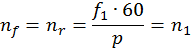 ,
,
- where nf is the rotational speed of the magnetic field in the forward direction, rpm,
- nr is the rotational speed of the magnetic field in the opposite direction, rpm,
- f1 is stator current frequency, Hz,
- p is a number of poles pairs,
- n1 is the rotational speed of magnetic flux, rpm


The action of the fluctuating field on a rotating rotor
Consider the case when the rotor in a fluctuating magnetic flux has an initial rotation. For example, we manually spun the shaft of a single-phase motor, one winding of which is connected to an AC power grid. In this case, under certain conditions, the motor will continue to develop torque, since the rotor slip relative to the forward and reverse magnetic flux will be unequal.
Assume that the forward magnetic flux Фf, rotates in the direction of rotor rotation, and the reverse magnetic flux Фr in the opposite direction. Since, the rotational speed of the rotor n2 is less than the rotational speed of the magnetic flux n1, the slip of the rotor relative to the flux Фf will be:
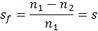 ,
,
- where sf is rotor slip relative to the forward magnetic flux,
- n2 is rotor speed, rpm,
- s is induction motor slip

The magnetic flux Фr rotates counter to the rotor rotation, the rotor rotation speed n2 relative to this flux is negative, and the slip of the rotor relative to Фr
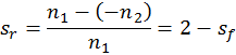 ,
,
- where sr is rotor slip relative to reverse magnetic flux


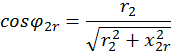
According to the law of electromagnetic induction, the forward Фf and reverse Фr magnetic fluxes generated by the stator winding induce EMF in the rotor winding, which, respectively, in the short-circuited rotor generate currents I2f and I2r. The frequency of the current in the rotor is proportional to the slip, therefore:
 ,
,
- where f2f is frequency of the current I2f induced by the forward magnetic flux, Hz
 ,
,
- where f2r is frequency of the current I2r induced by the reverse magnetic flux, Hz
Thus, when the rotor rotates, the electric current I2r induced by the reverse magnetic field in the rotor winding has a frequency f2r much higher than the frequency f2f of the rotor current I2f induced by the forward field.
the frequency of the current induced by the forward magnetic flux f2f = 2 Hz;
slip of the rotor relative to the reverse magnetic flux а sr = 1,96;
the frequency of the current induced by the reverse magnetic flux f2r = 98 Hz

According to Ampere's law, a torque occurs as a result of the interaction of the electric current I2f with the magnetic field Ff
 ,
,
- where Mf is the magnetic torque created by the forward magnetic flux, N∙m,
- сM is constant coefficient determined by the motor construction
The electric current I2r, interacting with the magnetic field Фr, creates a braking torque Mr directed against the rotation of the rotor, that is, opposite to the torque Mf:
 ,
,
- where Mr is magnetic torque created by reverse magnetic flux, N∙m
The resulting torque acting on the rotor of a single-phase induction motor,
 ,
,
The braking effect of the reverse field
When a single-phase motor is operating within the rated load, that is, at small slip values s = sf, the torque is generated mainly due to the torque Mf. The braking effect of the torque of the reverse field Mr slightly. This is due to the fact that the frequency f2r is much higher than the frequency f2f, therefore, the inductive reactance of the rotor winding а х2r = x2sr to the current I2r is much more than its active resistance. Therefore, the current I2r having a large inductive component has a strong demagnetizing effect on the reverse magnetic flux Фr, significantly weakening it.
 ,
,
- where r2 is rotor rods resistance, Ohm,
- x2r is reactive impedance of rotor rods, Ohm.
If we consider that the power factor is small, then it will become clear why the Mr under the load of the motor does not have a significant braking effect on the rotor of a single-phase motor.


The action of a fluctuating field on a fixed rotor
With a stationary rotor (n2 = 0) slip sf = sr = 1 and Mf = Mr, therefore the initial starting torque of a single-phase induction motor Mf = 0. To create the starting torque, it is necessary to bring the rotor in rotation in one direction or another. Then s ≠ 1, the equality of the torques Мf and Мr is violated and the resulting electromagnetic torque acquires some value M = Mf - Mr ≠ 0.
Starting of a single-phase induction motor. How to create an initial rotation?
One way to create a starting torque in a single-phase induction motor is to position the auxiliary (start) winding B, which is offset in space relative to the main (run) winding A at an angle of 90 electrical degrees. In order that the stator windings to create a rotating magnetic field, the currents IA and IB in the windings must be out of phase relative to each other. To obtain a phase shift between the currents IA and IB, the auxiliary (start) winding B is connected to a phase-shifting element, which is resistance (resistor), inductance (choke) or capacitance (capacitor) [1].
After the motor rotor accelerates to a rotational speed close to steady, the starting winding B is disconnected. The auxiliary winding is disconnected either automatically using a centrifugal switch, a time delay relay, a current or a differential relay, or manually using a button.
Thus, during start-up, the single-phase induction motor operates as two-phase, and after the start-up, as single-phase.
Single-phase induction motor connection
Resistance start induction motor
Resistance start induction motor is a split-phase motor, in which the auxiliary winding circuit is distinguished by increased resistance.


To start a single-phase induction motor, you can use a starting resistor, which is connected in series to the starting winding. In this case, it is possible to achieve a phase shift of 30° between the currents of the main and auxiliary windings, which is quite enough to start the motor. In a motor with starting resistance, the phase difference is explained by the different complex impedance of the circuits.
Also, a phase shift can be created by using a start winding with a lower inductance and higher resistance. For this, the starting winding is done with a smaller number of turns and using a thinner wire than in the main winding.
Capacitor start induction motor
Capacitor start induction motor is a split-phase motor, in which the auxiliary winding circuit with a capacitor is switched on only for the duration of the start.

Among phase shifting elements, only a capacitor allows achieving the best starting properties of a single-phase induction electric motor.
Motors in the circuit of which a permanently switched on capacitor use two phases for operation and are called capacitor ones. The working principle of these motors is based on the use of a rotating magnetic field.
Shaded pole single-phase induction motor
Shaded pole induction motor is a split-phase motor in which the auxiliary winding is short-circuited.
The stator of a shaded pole single-phase induction motor usually has salient poles. Each stator pole is divided into two unequal sections by an axial groove. A smaller section of the pole has a short-circuited turn. The rotor of a shaded pole single-phase motor is short-circuited in the form of a squirrel cage.
When the single-phase stator winding is turned on to the power grid, a fluctuating magnetic flux is created in the motor magnetic circuit. One part of which passes through unshaded Ф', and the other Ф" along the shaded section of the pole. Flow Ф" induces EMF Ek in a short-circuited turn, resulting in a current Ik lagging from Ek in phase due to the inductance of the coil. The current Ik creates a magnetic flux Фk, directed oppositely to Ф", creating the resulting flux in the shaded section of the pole Фs=Ф"+Фk. Thus, in a motor, the flows of the shaded and unshaded sections of the pole are shifted in time by a certain angle.
The spatial and temporal shear angles between the flows Фs and Ф' create conditions for a rotating elliptical magnetic field to appear in the motor, since Фs ≠ Ф'.
Starting and working properties of the considered motor are low. Efficiency is much lower than that of capacitor start induction motors of the same power, which is associated with significant electrical losses in a short-circuited coil.
Single-phase induction motor with asymmetrical stator

The stator of such a single-phase motor is made with salient poles on a non-symmetrical laminated core. The rotor has squirrel-cage winding.
This motor for an operation does not require the use of phase-shifting elements. The disadvantage of this motor is low efficiency.