Vector control of motor
The main idea of vector control is to control not only the magnitude and frequency of the supply voltage but also the phase. In other words, the magnitude and angle of the space vector are controlled [1]. Vector control in comparison with the scalar has a higher performance. Vector control eliminates almost all the disadvantages of scalar control.
- Advantages of vector control:
- high accuracy of speed control;
- soft start and smooth motor rotation in full speed range;
- fast response to a load change: when there is a load change, there is practically no change in the speed;
- increased control range and regulation accuracy;
- losses for heating and magnetization are reduced, the efficiency of the electric motor increases.
- The disadvantages of vector control include:
- the need to set motor parameters;
- large speed fluctuations at constant load;
- large computational complexity.

A general block diagram of a high-performance speed control system for a brushless AC motor is shown in the figure above. The circuit is based on the flux and torque control loops, together with the estimator unit, which can be implemented in various ways. At the same time, the external speed control loop is largely unified and generates control signals for torque M* and flux Ψ* (through the flux program unit) regulators. The motor speed can be measured by a mechanical sensor (speed/position) or obtained by means of a program estimator that allows you to implement sensorless control.
Classification of vector control methods
Since the seventies of the twentieth century, many ways to control the torque have been proposed. Not all of them are widely used in the industry. Therefore, in this article only the most popular control methods are considered. The discussed techniques of torque control are presented for control systems of asynchronous and permanent magnet synchronous motors with sinusoidal back EMF.
Existing torque control methods can be classified in various ways.
- Most often, the methods of torque control are divided into the following groups:
- linear (PI, PID) regulators;
- nonlinear (hysteresis) regulators.
| Control method | Speed control range | Speed error3, % | Torque rise time, ms | Starting torque | Cost | Description | ||
|---|---|---|---|---|---|---|---|---|
| Scalar | 1:101 | 5-10 | Not available | Low | Very low | It has a slow response when load changing and a small range of speed control, but it is easy to implement. | ||
| Vector | Linear | Field oriented control | >1:2002 | 0 | <1-2 | High | High | Allows you to smoothly and quickly control the basic parameters of the motor - torque, and speed. This method requires information about the position of the rotor. |
| DTC-SVM | >1:2002 | 0 | <1-2 | High | High | A hybrid method designed to combine the benefits of the FOC and DTC. | ||
| Nonlinear | Switching Table based Direct Torque Control | >1:2002 | 0 | <1 | High | High | It has a high dynamics and a simple scheme, but a characteristic feature of its work is high current and torque ripples. | |
| Direct Self Control | >1:2002 | 0 | <1-2 | High | High | It has an inverter switching frequency lower than other methods and is designed to reduce losses when controlling high power motors. | ||
- Open loop
- Closed loop
- In steady state
Among vector control, the most widely used are field oriented control and direct torque control.
Linear torque controllers
Linear torque controllers work in conjunction with voltage pulse width modulator (PWM). The regulators determine the required stator voltage vector, averaged over the sampling period. The voltage vector is finally synthesized by the PWM method, in most cases, the space vector modulation (SVM) is used. Unlike nonlinear torque control schemes, where signals are processed on instantaneous values, in linear torque control schemes, the linear controller (PI) works with values averaged over the sampling period. Therefore, the sampling rate can be reduced from 40 kHz for nonlinear torque controllers to 2–5 kHz in linear torque control schemes.
- The group of linear regulators include the following methods of torque control:
- field oriented control (FOC);
- direct torque control with voltage space vector modulation (DTC-SVM);
- direct torque control with flux vector modulation (DTC-FVM).
Field oriented control
The field oriented control proposed in 1970 by Blaschke [3] and Hasse [4] is based on an analogy with a mechanically commutated separately excited brushed DC motor. In this motor, the excitation and armature windings are separated, the flux is controlled by the inductor excitation current, and the torque is independently controlled by the armature current regulation. Thus, the currents of the flux and the torque are electrically and magnetically separated.

- The scheme is shown in a simplified form.
Detailed diagram of sensorless field oriented control of PMSM with salient pole rotor.
On the other hand, brushless AC motors (SCIM, PMSM) most often have a three-phase stator winding, and the stator current vector Is is used to control both the flux and torque. Thus, the excitation current and armature current are combined into a stator current vector and cannot be controlled separately. The decoupling can be achieved mathematically by decomposing the instantaneous value of the stator current vector Is into two components: the direct component of the stator current Isd (creating the field) and the quadrature component of the stator current Isq (creating torque) in the rotating dq coordinate system oriented to the rotor flux (R -FOC - rotor flux-oriented control) - figure above. Thus, the control of the brushless AC motor becomes identical to the control of the separately excited DC motor and can be implemented using a PWM inverter with a linear PI regulator and voltage space vector modulation.
In the field oriented control, the torque and flux are controlled indirectly by controlling the components of the stator current vector.
The instantaneous values of the stator currents are converted to dq rotating coordinate system by using the Park transform αβ/dq, which also requires information about the position of the rotor. The flux is controlled through the direct component of the current Isd, while the torque is controlled through the quadrature component of the current Isq. The inverse Park transform (dq/αβ), the mathematical module of coordinate transformation, allows you to calculate the reference components of the voltage vector Vsα* и Vsβ*.

To determine the rotor position, either the rotor position sensor (RPS) installed in the electric motor or the sensorless control algorithm implemented in the control system is used, which calculates the rotor position information in real time based on the data available in the control system.
Direct Torque Control with Space Vector Modulation
- Direct Torque Control with Voltage Space Vector Modulation
- Direct Torque Control with Flux Vector Modulation
Direct Torque Control with Space Vector Modulation operating in the stator reference frame, therefore, this control does not require information about the rotor position.
In particular, this method implements sensorless control of a permanent magnet synchronous motor in the entire speed range, including low speed, without the need to high-frequency signal injection and change the rotor design, as is done in sensorless field-oriented control of a permanent magnet electric motor.
Direct Torque Control with Voltage Space Vector Modulation
The block diagram of direct torque control with space vector modulation (DTC-SVM) with closed loop torque and flux regulation operating in a Cartesian coordinate system oriented along the stator flux is shown in the figure below. The outputs of PI torque and flux controllers are interpreted as the reference components of the stator voltage Vψ* and VM* in the dq coordinate system oriented by the stator flux (stator flux-oriented control, S-FOC). These commands (DC voltages) are then converted into a stationary coordinate system αβ, after which the control values Vsα* and Vsβ* arrive at a module of space vector modulation (SVM).

Note that this scheme can be considered as a simplified stator flux oriented control (S-FOC) without a current control loop or as a classical switching table direct torque control scheme (ST DTC) in which the switching table is replaced by a modulator (SVM), and the hysteresis torque and flux controllers are replaced by linear PI regulators.
In the scheme of direct torque control with space vector modulation (DTC-SVM), the torque and the flux are directly controlled in a closed loop, so an accurate estimate of the flux and torque is needed. In the scheme of direct torque control with space vector modulation (DTC-SVM), the torque and flux are directly controlled in a closed loop, so an accurate estimation of the flux and torque is needed. Unlike the classical hysteresis direct torque control algorithm, DTC-SVM operates at a constant switching frequency. This greatly improves the characteristics of the control system (drive): reduces the torque and flux ripples, allows you to confidently start the motor and operate at low speed. But this reduces the dynamic characteristics of the drive.
Direct Torque Control with Flux Vector Modulation
Direct Torque Control with Flux Vector Modulation (DTC-FVM) is a simplified version of Direct Torque Control with voltage Space Vector Modulation. In this case, the actual torque is estimated directly in the stationary reference frame so that transformation from synchronous to rotational reference frame (αβ -> dq) is not necessary.

To control the torque of the electric motor, a PI controller is used that regulates an increment in the torque angle Δδ at a given torque error ΔM at the input. The PI controller is used due to the fact that the relationship between the change in the torque ΔM and the increment in the torque angle Δδ is complex and nonlinear [7]. Then, an increment in the torque angle Δδ added to to the stator flux position θs in the stator reference frame α, β, to calculate the stator flux vector command ψs*. The obtained value of the stator flux vector command is compared with the estimated flux, after which the obtained error Δψs is used by the FVM unit for calculating the commanded stator voltage vector and calculating the inverter switching states [8]. In this scheme, due to the presence of the stator flux control loop used to calculate Δψs, the use of a PI flux controller is not required.
Nonlinear torque controllers
The presented group of torque regulators departs from the idea of coordinate transformation and control, by analogy with a brushed DC motor, which is the basis for field oriented control. Nonlinear regulators propose to replace the decoupling control with the bang-bang (hysteresis) control, which corresponds to the on/off work ideology of the semiconductor devices of the inverter.
In comparison with field oriented control, direct torque control schemes have the following characteristics:
- Advantages:
- simple control scheme;
- there is no current loops and direct current regulation;
- coordinate transformation is not required;
- there is no separate voltage modulation;
- position sensor is not required (sensorless control);
- good dynamics.
- Disadvantages:
- an accurate estimation of the stator magnetic flux vector and torque is required;
- the strong torque and current ripples due to non-linear (hysteresis) controller and variable frequency switching;
- noise with a wide range due to a variable switching frequency.
- The group of nonlinear torque regulators includes:
- switching table based direct torque control (DTC);
- direct self control (DSC);
- model predictive direct torque control;
- neural networks ;
- fuzzy logic controllers.
Direct torque control
For the first time, a switching table based direct torque control (ST-DTC) method was described by Takahashi and Noguchi in an IEEJ article submitted in September 1984 and later in an IEEE article published in September 1986 [5]. The scheme of the classical method of direct torque control (DTC) is much simpler than that of the field oriented control method (FOC), since it does not require the transformation of coordinate systems and measurement of the rotor position. The diagram of the direct torque control method (figure below) contains the torque and stator flux linkage estimator, torque and flux hysteresis comparators, switching table and inverter.
The principle of the method of direct torque control is the choice of the voltage vector for simultaneous control of both the torque and the stator flux linkage. The measured stator currents and inverter voltage are used to estimate the flux linkage and torque. Estimated stator flux linkage  and torque
  values are compared with the control signals for stator flux linkage ψs* and motor torque M*, respectively, by means of a hysteresis comparator. The required motor control voltage vector is selected from the switching table based on the digitized flux dΨ and torque dM errors generated by hysteresis comparators, as well as from the position sector
  of the stator flux vector derived from the angular position
 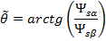 . Thus, the pulses SA, SB, and SC to control the inverter power switches are generated by selecting a vector from the table.

- Characteristic features of the ST-DTC scheme:
- sinusoidal waveforms of stator flux and currents with a harmonic content determined by the hysteresis tolerance bands of the flux and torque regulators;
- excellent torque dynamics;
- the hysteresis bands of the flux and torque determine the switching frequency of the inverter, which varies with changing synchronous speed and load [2].
There are many modifications of the classic ST-DTC scheme aimed at improving start-up, overload conditions, working at very low speeds, reducing torque ripple, working at the variable switching frequency and reducing the noise level.
The disadvantage of the classical method of direct torque control is the presence of high ripples of currents and torque in the steady state. The problem is eliminated by increasing the operating frequency of the inverter above 40 kHz, which increases the total cost of the control system [1].
Direct self control
An application for a patent of the method of direct self control was filed by Depenbrock in October 1984 [6]. The block diagram of the direct self control is shown below.
Based on the stator flux linkage commands ψs* and the actual phase components ψsA, ψsB and ψsC, the flux linkage comparators generate digital signals dA, dB and dC, which correspond to active voltage states (V1 – V6). The hysteresis torque controller has the output signal dM, which determines the zero states. Thus, the stator flux linkage regulator sets the time interval of active voltage states, which move the stator flux vector along a given trajectory, and the torque controller determines the time interval of zero voltage states that maintain the motor torque in the defined-by-hysteresis tolerance band.

- Characteristic features of the direct self control scheme are:
- non-sinusoidal waveforms of stator flux and current;;
- the stator flux vector moves along a hexagon path;
- there is no supply voltage reserve, and the inverter capabilities are fully utilized;
- the inverter switching frequency is lower than that of switching table based direct torque control;
- excellent dynamics in constant and weakening field regions.
Note, that the operation of the direct self control method can be reproduced using the ST-DTC scheme with flux hysteresis of 14% wide.
- Cristian Busca. Open loop low speed control for PMSM in high dynamic application.- Aalborg, Denmark.: Aalborg universitet, 2010
- Marian P. Kazmierkowski, Leopoldo G. Franquelo, Jose Rodriguez, Marcelo A. Perez, Jose I. Leon. High-Performance Motor Drives: IEEE Industrial Electronics, vol. 5, no. 3, pp. 6-26, Sep.2011
- F. Blaschke. The principle of field-orientation as applied to the transvector closed loop control system for rotating-field machines: Siemens Rev., vol. 34, no. 1, pp. 217–220, 1972.
- K. Hasse. Drehzahlgelverfahren fur schnelle Umkehrantriebe mit strom-richtergespeisten Asynchron-Kurzchlusslaufermotoren: Reglungstechnik, vol. 20, no. 2, pp. 60–66, 1972.
- I. Takahashi, and T. Noguchi. A new quick response and high-efficiency control strategy of an induction motor: IEEE Trans. Ind. Applicat., vol. IA-22, no. 5, pp. 820–827, Sept./Oct. 1986.
- M. Depenbrock. Direct self control of the flux and rotary moment of a rotary-field machine: US4678248, 1987.
- L. Xu, and M. Fu. A sensorless direct torque control technique for permanent magnet synchronous motors: IEEE Industry Applications Conference, 1999
- G. S. Buja and M. P. Kazmierkowski. Direct torque control of PWM inverter-fed AC motors — A survey: IEEE Trans. Ind. Electron, 2004