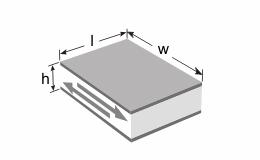
Piezo element
Structurally, the piezoelectric element is a piezo-ceramic with coated electrodes. Piezo elements can be of various shapes: in the form of disks, rings, tubes, plates, spheres, etc. For vibrators and generators, piezo elements are combined into piezo stacks to achieve the best performance.
Diameter: 10 mm
Thickness: 1 mm
Material: CTS-26
Voltage: 5V
Excitation frequency: 1MHz
Oscillation scale:: 30000:1
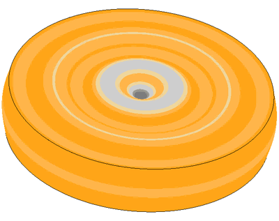
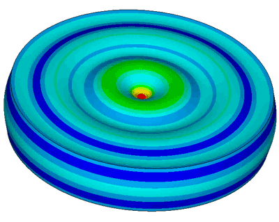
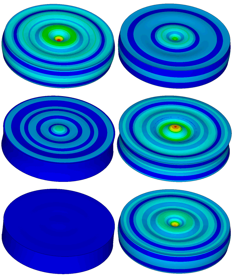
Piezoelectric effect
Piezoelectric substances (piezoelectrics), in particular, piezoelectric ceramics, have the property that during deformation under the action of external mechanical pressure, electric charges appear on their surface. This effect is called the direct piezoelectric effect and was discovered in 1880 by the Curie brothers.
Shortly thereafter (in 1881), the inverse piezoelectric effect was confirmed, namely, that such a substance located between two electrodes reacts to an applied voltage across it by changing its shape. The first effect is currently used for measurements, and the second for the excitation of mechanical pressures, deformations, and oscillations.
More detailed studies of the piezoelectric effect showed that it is explained by the property of the unit cell of the material structure. In this case, the unit cell is the smallest symmetric unit of material, from which a microscopic crystal can be obtained by its repeated repetition. It was shown that a necessary pre-condition for the appearance of the piezoelectric effect is the absence of a center of symmetry in the unit cell.
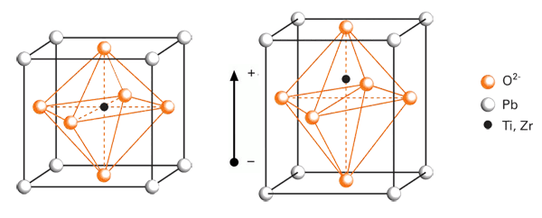
Here we can briefly explain the piezoelectric effect by the example of barium titanate, often used piezoelectric ceramics with a relatively simple unit cell design. The barium titanate BaTiO3, like many other piezoceramic substances, is similar in structure to perovskite (СаТiО3), by which this class of materials is named. The unit cell at temperatures above the critical, which is also called the Curie point, is cubic. If the temperature is below this critical one, then the unit cell is distorted tetragonally towards one of the edges. As a result, the distances between positively and negatively charged ions also change (Figure 1, for BaTiO3 instead of Pb - Ba). The displacement of ions from their initial position is very small: it makes up a few percents of the unit cell parameter. However, such a displacement leads to a separation of the centers of gravity of the charges inside the cell, so that an electric dipole moment appears. According to the energy conditions, the dipoles of neighboring unit cells of a crystal are ordered by regions in the same direction, forming the so-called domains.
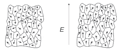
The polarization directions of domains are distributed in a polycrystalline structure according to a static law. Thus, unordered accumulations of individual microcrystals in the structure of matter, which are formed only in sintered ceramics, in the macroscopic sense, cannot produce any piezoelectric effect. The use of piezoelectric properties of unit cells is possible only after the so-called polarization process, in which a larger number of domains are aligned parallel to each other under the action of a strong electric field imposed on ceramics. Polarization is usually carried out at a temperature slightly below the Curie temperature in order to facilitate the orientation of the domains. After cooling, this ordered state remains stable.
Modern design tools allow you to calculate / model separately the piezoelectric element or the entire piezoelectric transducer. In coordination with "Engineering solutions", you can order parameters calculation of the piezoelectric transducer
Mechanical compression or tension, acting on a piezoelectric plate parallelly to the direction of polarization, leads to the deformation of all unit cells. In this case, the centers of gravity of the charges are mutually displaced inside the unit cells, which are now predominantly parallel, and the result is a charge on the surface [2].
Piezoelectric constitutive equations
Polarized piezoelectric materials are characterized by several coefficients and relationships. The four possible forms for piezoelectric constitutive equations are shown below [13]:
-
Stress - Charge form
-
Stress - Voltage form
-
Strain - Charge form
-
Strain - Voltage form
- where {T} is 6x1 mechanical stress vector, Pa,
- {S} is 6x1 mechanical strain (elastic deformation) vector, m/m,
- {D} is 3x1 the electric charge density displacement (electric displacement field, electric flux density, dielectric displacement) vector, C/m2,
- {E} is 3x1 electric field vector, V/m,
- [cE/D] is 6x6 elastic stiffness coefficient (for E/D = constant) matrix, N/m2
- [sE/D] is 6x6 elastic compliance coefficient (for E/D = constant) matrix, m2/N,
- [εS/T] is 3x3 dielectric permittivity (for S = constant/T = 0) matrix, F/m,
- [e] is 3x6 piezoelectric stress coefficient matrix, C/m2 or N/Vm,
- [h] is 3x6 piezoelectric deformation coefficient matrix, N/C or V/m,
- [d] is 3x6 piezoelectric strain (charge) coefficient matrix, C/N or m/V,
- [g] is 3x6 piezoelectric voltage or pressure constant matrix, m2/C or Vm/N,
- t (superscript) is transposed matrix
Properties of piezoceramics
The relationship between the applied force and the resulting response of the piezoelectric element depends on: the piezoelectric properties of piezoceramic, the size and shape of the sample, the direction of electrical and mechanical excitation.
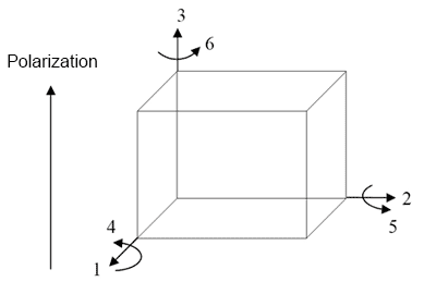
By their nature, piezoelectric materials are anisotropic crystals. Figure 3 shows the different directions and orientation axes of the piezoelectric material. Axes 1, 2 and 3 are the corresponding analogs of the X, Y, Z axes of the classical orthogonal coordinate system, while the axes 4, 5, and 6 define the axes of rotation. The direction of axis 3 is the direction of polarization [1]. This direction is established during production by means of a high constant voltage that is created between the electrodes.
a) Relative dielectric constant
The relative dielectric constant is the ratio of the dielectric permittivity of the material (in this case and
and  ) to the dielectric permittivity of a vacuum (ε0).
 and
and  ,
,
where ε0 = 8,85· 10-12, F/m
The superscript shows the boundary conditions acting on the material in the process of determining the value of the relative dielectric constant. In particular, the index T (in this case) says that the dielectric constant is measured on a free (not clamped) sample [3]. And the S index shows that measurements occur when the piezoelectric ceramics are constantly deformed (in the clamped state). The first subscript indicates the direction of the dielectric displacement, and the second - the electric field [1]. The formula for calculating the relative dielectric constant is as follows:
 ,
,
- where
 - dielectric permittivity (one of two
  or
or  ), F/m
 - t – distance between electrodes, m,
- A – area of the electrode, m2,
- C – capacitance, F
 ,
,
where с – speed of sound in the material, m/s [2]
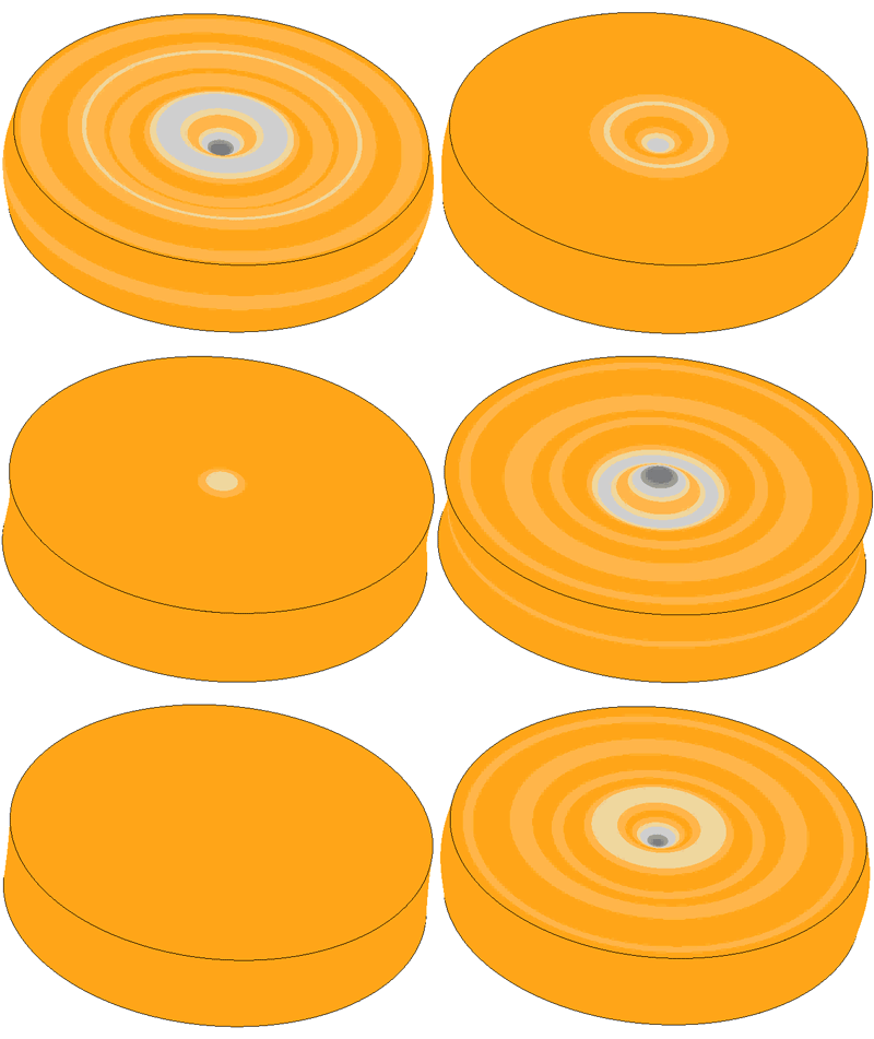
Oscillation scale 200000:1
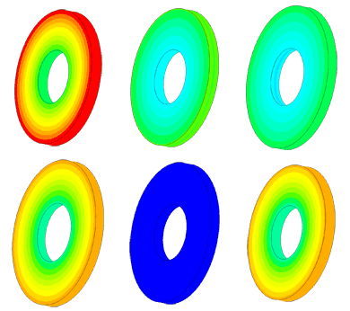

Oscillation scale 10000:1
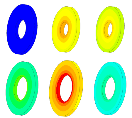

Oscillation scale 10000:1
c) Electromechanical coupling constant
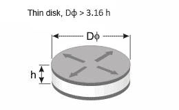
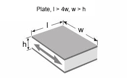
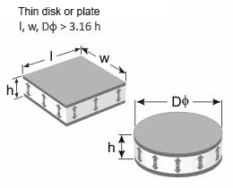
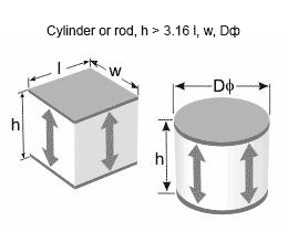
The electromechanical coupling coefficients kp, k33, k15, kt and k31 describe the ability of the piezoelectric element to convert energy from electrical to mechanical and vice versa.The square of the electromechanical coupling coefficient is defined as the ratio of the accumulated converted energy of one type (mechanical or electrical) to the input energy of the second type (electrical or mechanical). The index shows the relative directions of electrical and mechanical quantities and the type of oscillations. They can be associated with the mode of oscillations of a simple transducer of a certain shape. Planar coupling coefficient kp means the interconnection of electrical and mechanical energy in a thin circular disk polarized in thickness and oscillating in the radial direction — a planar mode (Figure 5a). Transverse coupling coefficient k31 refers to a long thin bar with electrodes on a long surface. The type of oscillations - tensile and compressive strain in length (Figure 5b). Thickness coupling coefficient kt is associated with a thin disk or plate and determines the tensile and compression in thickness (Figure 5c). Longitudinal coupling coefficient k33 corresponds to a long thin bar with electrodes at its ends and polarized in length. The type of oscillations is tensile and compression lengthwise (Figure 5d). Shear coupling coefficient k15 describes the energy converted to shear oscillations in thickness (Figure 5e) [4].This coefficient can be calculated through the resonant and antiresonant frequency by the formula.
 ,
,
- where fr – resonant frequency, Hz,
- fa – antiresonant frequency, Hz [5]
To measure these frequencies, an impedance analyzer is usually used, with which it is possible to obtain the dependence of impedance on the frequency of piezoelectric ceramics (Figure 6).
By nature, the resonant frequency occurs when the system has very little resistance, while antiresonance occurs when the system has very high resistance. In Figure 6, a frequency that has a minimum impedance is considered resonant (fr), and the frequency with maximum impedance - antiresonant (fa).
Figure 5 – Types of oscillation samples of piezoceramics of different shapes
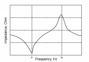
Figure 6 - The dependence of impedance on the frequency of piezoceramics [6]
 ) or elastic stiffness (
 ). Elastic compliance determines the amount of strain due to an applied mechanical stress. Due to the fact that under the influence of mechanical stress, the ceramic generates an electrical response, which counteracts the resultant strain, the effective Young's modulus for a short circuit of electrodes is less than at open circuited. In addition, the stiffness is different in different directions, so electrical and mechanical conditions are indicated for accurate determination of the magnitude. The superscript E indicates that measurements occur at a constant electric field (short circuit). While the superscript D indicates the boundary condition of
the constant dielectric displacement, i.e. measurements occur at open circuit. The first digit in subscript shows the direction of strain, the second subscript indicates the direction of mechanical stress [4].
- There are four piezoelectric constants [10]:
- d [C/N] or [m/V] - piezoelectric strain or charge coefficient;
- e [C/m2] or [N/Vm] - piezoelectric stress coefficient;
- g [m2/C] or [Vm/N] - piezoelectric voltage or pressure coefficient;
- h [N/C] or [V/m] - piezoelectric deformation coefficient.
- where D is the electric charge density displacement (electric displacement field, electric flux density, dielectric displacement), C/m2,
- E is electric field, V/m,
- T is mechanical stress, Pa,
- S is mechanical strain (elastic deformation),
- i (subscript) mean electrodes are perpendicular to "i" axis,
- j (subscript) mean that applied stress, or piezoelectrically induced strain, is in "j" direction.
The piezo modulus dij (piezoelectric strain or charge coefficient) – is the ratio of the mechanical strain to the applied electric field or of induced electric charge to mechanical stress (C/N) [2]
 ,
,
- where Δxs is the change of plate thickness, m,
- Us is the applied voltage, V
It is useful to remember that large dij values lead to large mechanical strain, which is usually achieved when designing ultrasonic transducers. d33 is used when the force is directed in the direction of the polarization axis (figure 5d). d31 is used when a force is applied at a right angle to the polarization axis, herewith a charge appears at the electrodes, just as in the previous case (figure 5b). d15 indicates that the charge is accumulated on the electrodes that are at right angles to the original polarizing electrodes and that the resulting mechanical oscillations are shear (figure 5e).
The piezo modulus eij (piezoelectric stress coefficient) is the ratio of the developed stress to the applied electric field.
 , [10]
- where cii is the material's elastic stiffness constant under conditions of constant electric field, Pa
The piezo modulus gij (piezoelectric pressure constant) is the ratio of the received voltage to the applied pressure.
 ,
,
- where Ue – received voltage, V,
- t - the thikness, m,
- px – applied pressure, Pa.
Index “33” shows that the electric field and mechanical stress are directed along the polarization axis. The “31” index means that the pressure is applied at a right angle to the polarization axis, and the voltage is received from the same electrodes as in the case of “33”. The index “15” implies that the applied voltage is shear and the resulting electric field is perpendicular to the polarization axis. A high value of gij leads to high output voltages, which is desirable for sensors.
The piezo modulus hij (piezoelectric deformation coefficient) is the ratio of the received voltage to the external change in thickness (developed strain).
 , [11]
- where Ue is the resultant voltage across the piezoelectric element, V,
- Δxe is an external change in thickness, m.
 ,
,
- where µ is Poisson’s ratio,
- Δa is the absolute increment of thickness, m,
- a is thickness after deformation, m,
- Δl is the absolute increment of length, m,
- l is length after deformation, m
 ,
,
- where αf is the temperature coefficient of resonant frequency (TCF), ppm/˚С,
- f(t1) is the resonant frequency at t1, Hz,
- f(t2) is the resonant frequency at temperature t2, Hz,
- f20 is the resonant frequency at temperature of 20˚С, Hz,
- Δt is the temperature difference Δt = t2 - t1, ˚С
 ,
,
- where αC is the temperature coefficient of capacitance (TCC), ppm/˚С,
- C(t1) is capacity at temperature t1, F,
- C(t2) is capacity at temperature t2, F,
- C20 capacity at a temperature of 20˚С, F
 ,
,
- where αl is the coefficient of linear thermal expansion (CLTE), ppm/˚С,
- l(t1) is length at temperature t1, m,
- l(t2) is length at temperature t2, m,
- l20 is length at temperature of 20˚С, m
 ,
,
- where AR is the aging rate for resonant frequency or static capacitance,
- t1, t2 is number of days aged after polarization,
 ,
,  is resonant frequency or static capacitance through t1 and t2 days after polarization
Q-factor is a quantitative characteristic of the resonant properties of oscillatory systems, indicating how many times the amplitude of forced oscillations at resonance exceeds the amplitude of forced oscillations at a frequency much lower than the resonant one with the same amplitude of the exciting force [8]. The quality factor is equal to the ratio of the natural frequency ω of the resonant system to the width Δω of the frequency band, at the boundaries of which the energy of the system at forced oscillation is half the energy at the resonant frequencies.
 ,
,
- where Qm – mechanical quality factor,
- fr is the resonant frequency, Hz,
- fa is the antiresonant frequency, Hz,
- Zr is the resonant resistance, Ohm,
- С is static capacitance, F
Products based on piezoelectric resonance require high mechanical Q-factor.
Curie temperature is the temperature above which the piezoelectric material loses its properties [2]. ,
,
- where ρ – density, kg/m3,
- m – mass, kg,
- V – volume, m3.
Manufacture of piezo elements
Most of the compositions of piezoelectric ceramics based on chemical compounds with formula ABO3 (for example, BaTiO3, PbTiO3) with a perovskite-type crystal structure and different solid solutions on their basis (e.g., systems BaTiO3 — CaTiO3, BaTiO3 — CaTiO3 — CoCO3, NaNbO3 — KNbO3). Particularly widely used as piezoelectric materials are compounds of the РbТiO3 — PbZrO3 system (the so-called PZT system). Of practical interest is also a number of compounds with the formula AB2O6, for example PbNb2O6, having a very high Curie point (~570 °С), which allows you to create piezoelectric elements for operation at high temperatures.
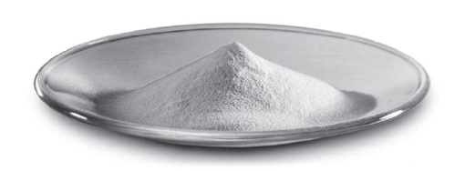
The process of manufacturing piezoceramics is divided into several stages. When synthesizing a given ferroelectric compound, the raw materials (oxides or salts, for example, titanium dioxide and barium oxide) are milled and mixed in amounts corresponding to the stoichiometric composition of the compound, and then subjected to heat treatment at temperatures of 900 - 1300 °C, during which is a chemical synthesis. A so-called method of precipitation from aqueous solutions is also used, at which the temperature of synthesis decreases to 750 - 1000 °C due to ideal mixing of the components. Blanks for future piezo elements of the required configuration and dimensions are obtained from the powdery synthesized material by pressing (as well as by injection molding), which are then sintered at a strictly defined temperature regime, which largely determines the properties of piezoceramics. The machining (grinding, lapping, polishing, and sawing) of the part after sintering provides it with precisely defined shape and dimensions. Electrical connections are usually made by applying silver, nickel, platinum electrodes in a screen printing process with subsequent sintering at approximate 600°C. For the polarization of ceramics, an electrical voltage is applied to the electrodes (field strength E is from 0.5 to 3 kV/mm depending on the chemical composition and polarization method). In order to reduce the field strength E, during polarization, the sample is heated to temperatures close to the Curie point (because the domains are more mobile), and then slowly cooled in the presence of a field. Aging, i.e. change in parameters (dielectric constant, piezo modules) with time, is characteristic of piezoceramics, especially noticeable in the first few days after fabrication and polarization of samples, which is caused by a change in both the mechanical stresses at the grains boundaries and the residual polarization [8].
Piezoceramics application
Piezoelectric materials have found application in a wide range of areas, such as medical instruments, control of industrial processes, semiconductor manufacturing systems, household electrical appliances, communication control systems, various measuring instruments, and other areas. Commercial systems that use piezoelectric materials - pumps, sewing machines, sensors (pressure, icing, angular velocities, etc.), optical instruments, laser printers, motors for autofocus cameras, and many others. In this case, the scope of these materials is constantly growing. Using a piezoelectric element is usually reduced to four categories: sensors, generators, power actuators, and transducers.
In generators, piezoelectric materials can generate a voltage sufficient to cause a spark between the electrodes, and thus can be used as electrodes to ignite the fuel, for gas stoves and for welding equipment. Alternatively, the electrical energy generated by the piezoelectric elements may accumulate. Such generators are excellent solid batteries for electronic circuits.
In sensors, piezoelectric materials convert physical parameters such as acceleration, pressure, and vibrations into an electrical signal.
In actuators, piezoelectric materials convert an electrical signal into a precisely controlled physical displacement, clearly setting the accuracy of mechanical tools, lenses, and mirrors.
In transducers, piezoelectric transducers can both generate an ultrasonic signal from electrical energy and convert incoming mechanical vibrations into electrical ones. Piezoelectric instruments are designed to measure distance, flow rate, and fluid level. Transducers are also used to generate ultrasonic vibrations for cleaning, drilling, welding, grinding ceramics and for medical diagnostics [1].
- Ranier Clement Tjiptoprodjo. On a Finite Element Approach to Modeling of Piezoelectric Element Driven Compliant Mechanisms.- Saskatchewan, Canada.: University of Saskatchewan Saskatoon, April 2005
- J. Krautkrämer, H. Krautkrämer. Ultrasonic Testing of Materials.- Moscow.: 1991.
- David H. Johnson. Simulation of an ultrasonic piezoelectric transducer for NASA/JPL Mars rover.- PA, USA.: Cybersonic, Inc. of Erie, 2003.
- www.piezo.com
- OST 11 0444-87 «Piezoceramic materials»
- Tokin. Multilayer Piezoelectic Actuators. User’s Manual, Tokin Corporate Publisher.: 1996.
- D.V.Sivuhin. General course of physics. P.I. Mechanics.- Moscow.: 1979.
- Golyamina I.P. Ultrasound.-Moscow .: Soviet Encyclopedia, 1979
- Jan Tichy, Jiry Erhart, Erwin Kittinger, Jana Privratska. Fundamentals of Piezoelectric Sensorics.- Heidelberg, Dordrecht, London, New York.: Springer, 2010
- Yufeng Zhou. Principles and Applications of Therapeutic Ultrasound in Healthcare.: CRC Press, 2015
- Nicholas P. Cheremisinoff, Paul N. Flow Measurement for Engineers and Scientists.: CRC Press, 1987
- Frederic Giraud, Christophe Giraud-Audine. Piezoelectric Actuators: Vector Control Method: Basic, Modeling and Mechatronic Design of Ultrasound Devices.: Elsevier, 2019
- ANSI/IEEE Std 176-1987. IEEE Standard on Piezoelectricity.- New York.: IEEE Standards Board, 1987


