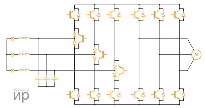
Variable frequency drive
A variable frequency drive is a device used to provide continuous process control. Typically a variable frequency drive is capable of controlling the speed and torque of induction and/or synchronous motors.
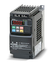
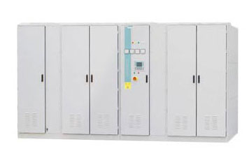
Variable frequency drive finds more and more widespread use in various industrial and transport applications. Due to the development of power semiconductor devices, voltage inverters and current inverters with PWM control are becoming more and more widespread. Devices that convert a DC signal into an AC signal with the desired voltage and frequency are called inverters. This conversion can be done with electronic switches (BJT, MOSFET, IGBT, MCT, SIT, GTO) and thyristors, depending on the task.
At the moment, the main part of all produced electrical energy in the world is used to feed electric motors. The conversion of electrical power into mechanical power is carried out using electric motors with a power of less than a watt to several tens of megawatts.
- Modern electric drives must meet various requirements such as:
- maximum efficiency;
- wide range of smooth setting of rotation speed, torque, acceleration, angle, and linear position;
- fast removal of errors when changing control and/or disturbance signals;
- maximum use of motor power during reduced voltage or current;
- reliability, intuitive control.
Variable frequency drive construction
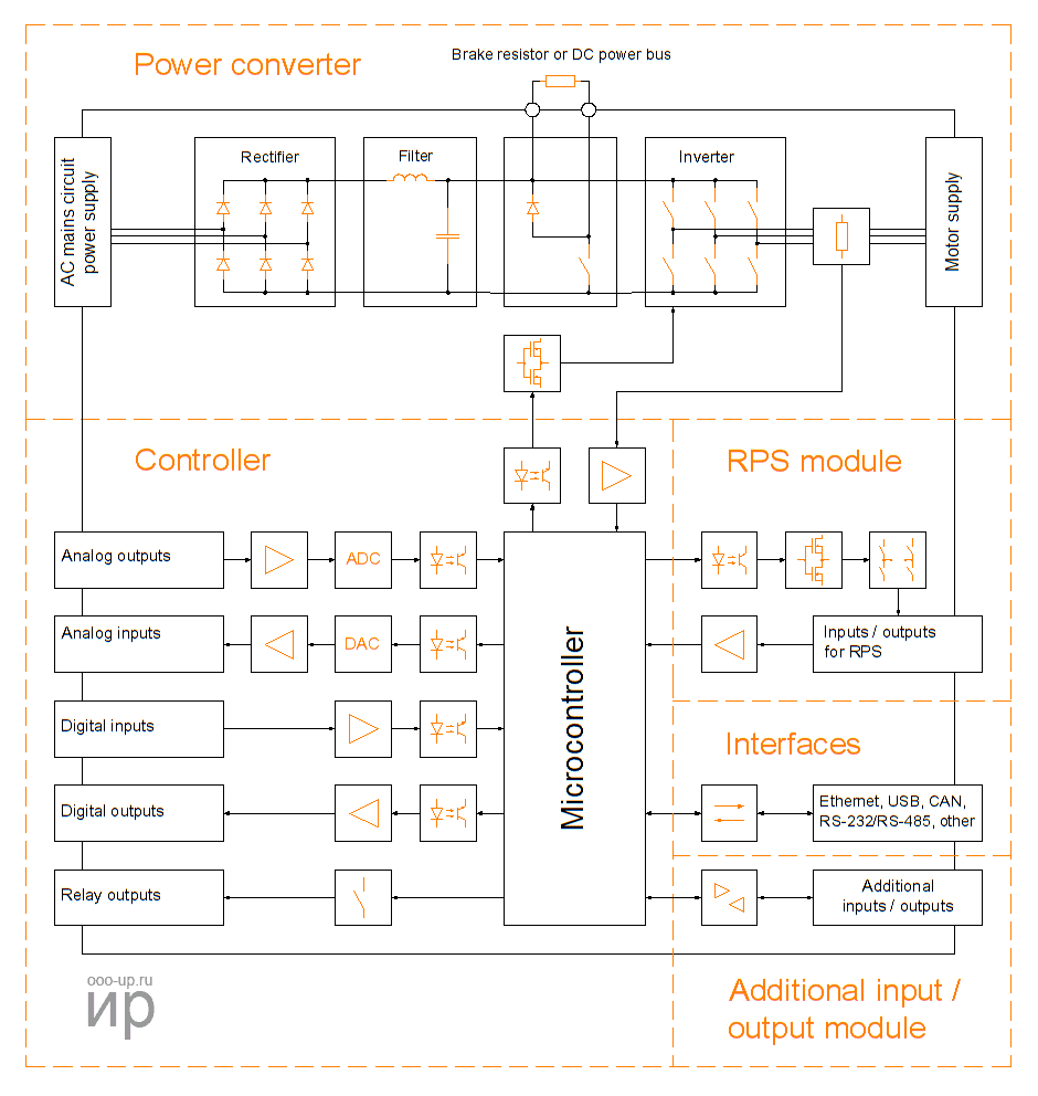
The main elements of the variable frequency drive are the power section (electrical energy converter) and the control device (controller). Modern variable frequency drives usually have a modular architecture, which allows expanding the capabilities of the device. It is also often possible to install additional interface modules and expansion modules for I/O channels.
Control techniques
The microcontroller of the variable frequency drive runs software that controls the main parameters of the electric motor (speed and torque). The main control methods of brushless motors used in variable frequency drives are presented in the table below.
| Control method | Speed control range | Speed error3, % | Torque rise time, ms | Starting torque | Cost | Standard applications | ||
|---|---|---|---|---|---|---|---|---|
| Scalar | 1:101 | 5-10 | Not available | Low | Very low | Low-performance: pumps, fans, compressors, HVAC (heating, ventilation, and air conditioning) | ||
| Vector | Linear | Field oriented control | >1:2002 | 0 | <1-2 | High | High | High-performance: cranes, elevators, transport, etc. |
| DTC with voltage SVM | >1:2002 | 0 | <1-2 | High | High | |||
| Nonlinear | Switching Table based Direct Torque Control | >1:2002 | 0 | <1 | High | High | ||
| Direct Self Control | >1:2002 | 0 | <1-2 | High | High | High performance: electric traction, fast field weakening | ||
- Open loop
- Closed loop
- In steady state
Modulation methods
The extensive development of power electrical converters in recent decades has led to an increase in the amount of research in the field of modulation. The modulation method directly affects the efficiency of the entire power system (power section, control system), determining the economic benefit and performance of the final product.
The main goal of modulation techniques is to achieve the best waveform (voltages and currents) with minimal loss. Other minor control tasks can be solved by using the correct modulation method, such as common-mode voltage reduction, dc voltage balancing, reducing input current ripple (harmonics), and slowing the slew rate. The simultaneous achievement of all control goals is impossible, a compromise is needed. Every power converter topology and each application must be studied in depth to determine the most appropriate modulation method.
- Modulation techniques can be divided into four main groups:
- PWM - Pulse Width Modulation
- SVM - Space Vector Modulation
- Harmonic Control Techniques
- Variable Frequency Modulation Techniques
Power converter topologies
The roots of power electronics go back to 1901, when P.C. Hewitt invented the mercury rectifier. However, the modern era of semiconductor power electronics began with the commercial introduction of a controlled silicon-controlled rectifier (thyristor) by General Electric in 1958. Then development continued in the field of new semiconductor structures, materials, and manufacturing, giving the market many new devices with higher power and improved performance. Power electronics today are built on metal-oxide-semiconductor field-effect transistors (MOSFETs) and Insulated-gate bipolar transistors (IGBTs), and for very high power ranges, on integrated gate-commutated thyristors (IGCT ). Integrated power modules are also available now. A new era of high voltage, high frequency, and high-temperature technologies is being opened by promising semiconductor devices based on a wide band gap silicon carbide (SiC) material. New power semiconductor devices always initiate the development of new converter topologies [3].
Voltage-source converter
The voltage inverter is the most common among power converters.
Two-level voltage-source inverter
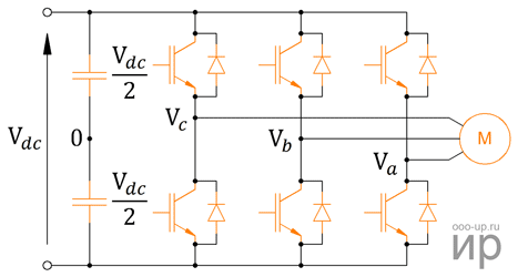
The two-level voltage-source inverter is the most widely used power converter topology. It consists of a capacitor and two power semiconductors per phase. The control signals for the upper and lower power switches are complementary and generates only two possible states of the output voltage (the load is connected to the positive or negative bus of the DC voltage source).
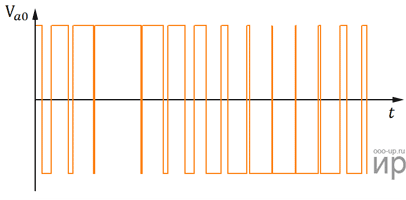
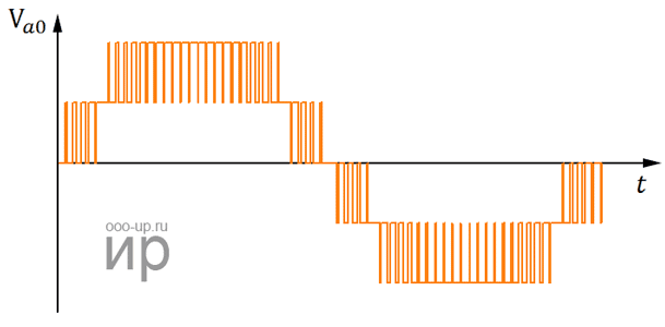
Using modulation techniques to generate gating pulses, it is possible to synthesize the output voltage with the desired parameters (form, frequency, amplitude). Due to the content of high harmonics in the output signal, the output signal must be filtered to generate sinusoidal currents, but since these converters usually have inductive loads (motors), additional filters are used only when necessary.
The maximum output voltage is determined by the DC link voltage value. A high DC link voltage is required to efficiently control high-power loads, but in practice, this voltage is limited by the blocking voltage of the semiconductors. For example, low voltage IGBTs provide output voltages of up to 690 V. In order to circumvent this voltage limitation, multilevel converter topologies have been developed in recent decades. These converters are more complex than two-level converters in terms of topology, modulation, and control, but at the same time, they have the best parameters in terms of power, reliability, dimensions (power density), performance, and efficiency.
Three-level neutral point clamped converter
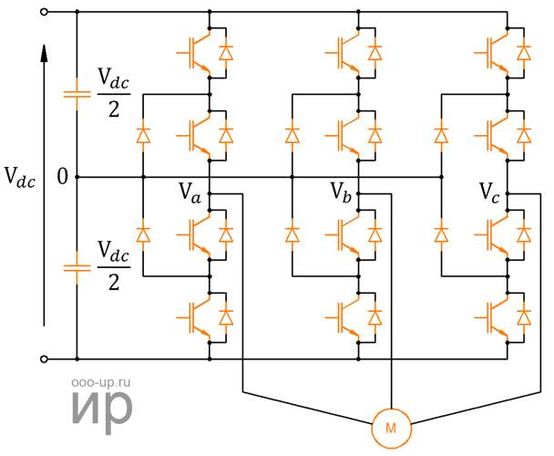
In a three-level neutral point clamped (3L-NPC) converter, the DC link voltage is divided equally by two capacitors, so the phase can be connected to the positive voltage line (by switching on the two upper switches), to the midpoint (by switching on the two central switches) or to the negative voltage line (by switching on the two lower switches). In this case, each switch needs to block only half of the DC link voltage, thereby allowing to increase the power of the device using the same semiconductor switches as in a conventional two-level converter. This converter usually uses high voltage IGBT transistors and IGCT thyristors.
- The disadvantages of these converters are:
- Capacitor unbalance creating asymmetry in the converter. It is proposed to solve this problem by changing the modulation method.
- Unequal distribution of losses due to the fact that the switching losses of outer and central switches differ depending on the mode of operation. This problem cannot be solved using the conventional circuit, so a modified topology was proposed - an active converter with a neutral point clamped (active NPC). In this scheme, the clamping diodes are replaced by controlled switches. Thus, by choosing the appropriate combination of switches, it is possible to reduce and evenly distribute losses.
- GOST R 50369-92 Electric drives. Terms and definitions.
- Rahul Dixit, Bindeshwar Singh, Nupur Mittal. Adjustable speeds drives: Review on different inverter topologies.- Sultanpur, India.:International Journal of Reviews in Computing, 2012.
- Marian P. Kazmierkowski, Leopoldo G. Franquelo, Jose Rodriguez, Marcelo A. Perez, Jose I. Leon, "High-Performance Motor Drives", IEEE Industrial Electronicsd, vol. 5, no. 3, pp. 6-26, Sep.2011.
A neutral point clamped converter can be scaled to achieve more than three output levels by dividing the DC link voltage by more than two by means of capacitors. Each of these divided DC link voltages can be connected to the load using an extended set of switches and clamping diodes. Along with the increased power, the advantages of a multi-level converter are better power quality, lower dv/dt, and associated electromagnetic interference. However, when a neutral point clamped transducer has more than three levels, other problems arise. In this case, the clamping diodes require a higher blocking voltage than the main switches, which requires the use of different technology or several clamping diodes connected in series. In addition, the unequal use of power components in the scheme becomes critical. As a result, due to the increase in the number of elements, reliability decreases. These disadvantages limit the use of neutral point clamped converters with more than three levels in industrial applications.
Multilevel converters
Сonverters based on modular power cells such as the cascaded H-bridge (CHB) converter and flying capacitor (FC) converter have been proposed to provide more levels of output voltage than neutral point clamped converter.
Cascaded H-bridge converter
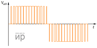
Cascaded H-bridge converter is a highly modular inverter consisting of several single-phase inverters, commonly called power cells, connected in series to form a phase. Each power cell is based on standard low voltage components, which makes them easy and cheap to replace in the event of a failure.
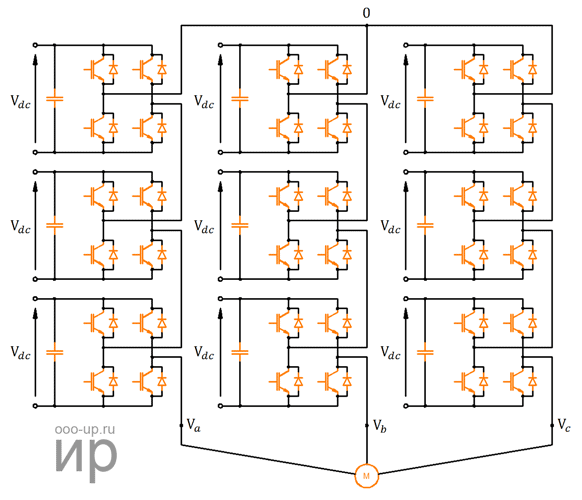
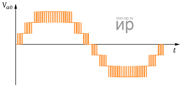
The main advantage of this converter is the use of only low-voltage components, while it allows you to control a high-power load in the medium-voltage range. Despite the fact that the switching frequency in each cell is low, the equivalent switching frequency applied to the load is high, which reduces switching losses, gives a low voltage slew rate (dv/dt), and helps to avoid resonances.
Flying capacitor converter
The output voltage of the flying capacitor converter is obtained by directly connecting the phase output to the positive or negative bars, or through the flying capacitors. The number of output voltage levels depends on the number of flying capacitors and the relationship between the different dc voltages.
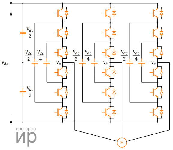
This converter, as in the case of the cascaded H-bridge converter, also has a modular topology, where each cell consists of a capacitor and two complementary switches. However, unlike a cascaded converter, adding additional power cells in the flying capacitor converter does not increase the converter's power rating, but only decreases the voltage slew rate (dv/dt), improving the harmonic distortion of the output signal. As with a cascaded H-bridge converter, modularity reduces component replacement costs, facilitates support, and allows for fault-tolerant operation.
The flying capacitor converter requires only one DC power supply to feed all cells and phases. Therefore, the input transformer can be excluded, and the number of cells can be arbitrarily increased depending on the required output power. Like a neutral point clamped converter, this converter requires a special control algorithm to regulate the voltage in the capacitors.
Current-source converter
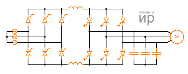
The current source inverter always requires a controlled rectifier to provide a constant current in the DC link. In standard topology, thyristor rectifiers are commonly used. To reduce noise in the load, a split inductance is used in the DC link. The current inverter has a power semiconductors arrangement similar to a voltage inverter, but integrated gate-commutated thyristors (IGCTs) are used as power switches. The output current is in the form of a PWM and cannot be directly applied to an inductive load (motor), so the current inverter necessarily includes an output capacitive filter that smooths the current and delivers a smooth voltage to the load. This converter can be implemented for operation at medium voltages and, moreover, by its nature, it has the ability energy recovery.
Direct converter
Direct converters transfer energy directly from input to output without the use of energy storage elements. The main advantage of such converters is their smaller dimensions. The disadvantage is the need for a more complex control scheme.
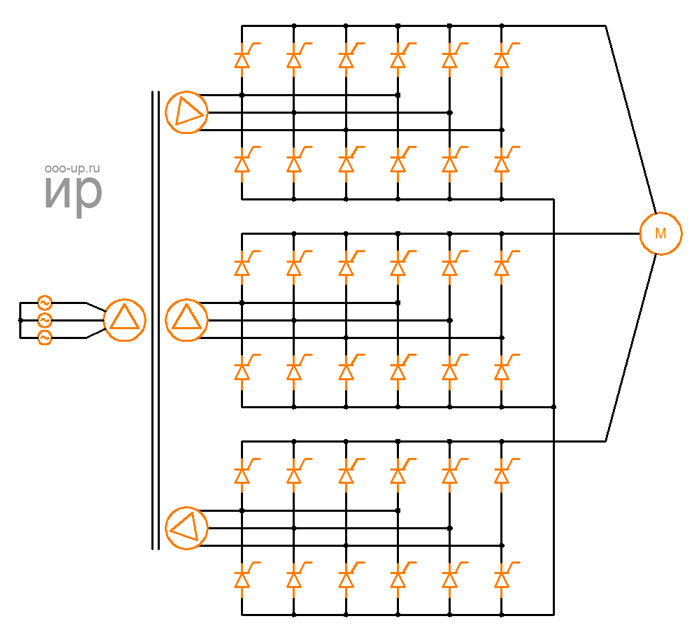
The cycloconverter belongs to the category of direct converters. This converter has been widely used in high-power applications. This converter consists of double thyristor converters per phase, which can generate a variable DC voltage, controlled to follow a sine wave reference. The input of each converter is powered by a phase-shifting transformer, which eliminates low-order input current harmonics. The output voltage is the result of a combination of input voltage segments in which the fundamental component follows the reference signal. By its nature, this converter is well suited for driving low-frequency high power loads.
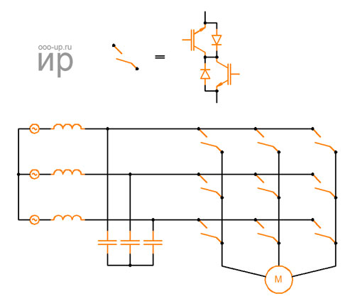
The matrix converter in its direct and indirect versions also belongs to the category of direct converters. The basic principle of operation of the direct matrix converter is the ability to connect the output phase to any of the input voltages. The converter consists of nine bidirectional switches that can connect any input phase to any output phase, allowing current to flow in both directions. To improve the input current is required a second-order inductive-capacitive filter. The output is directly connected to the inductive load. Not all available switches combinations are possible, they are limited to only 27 valid switching states. The main advantage of matrix converters is their smaller size, which is important for automotive and aviation applications.
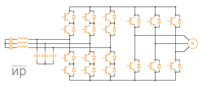
The indirect matrix converter (IMC) consists of a bidirectional three-phase rectifier, a virtual DC link, and a three-phase inverter. If the bidirectional switch is considered as two unidirectional switches, the number of power semiconductors in the indirect matrix converter and direct matrix converter is the same, but the number of possible switch-on states is different. If limit the operation of the indirect matrix converter from the positive voltage in the virtual DC link, it is possible to simplify its topology and reduce the number of elements using the same configuration. Such a reduced topology is called a sparse matrix converter (SMC).
