Synchronous reluctance motor
Construction of synchronous reluctance motor
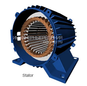
The stator of reluctance motor may be with distributed and with concentrated winding and consists of a frame and a core with a winding.
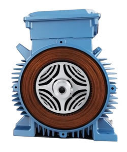
Three main types of the rotor of reluctance motor are distinguished: a rotor with salient poles, an axially laminated rotor, and a transversally laminated rotor.
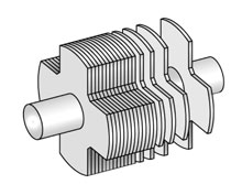
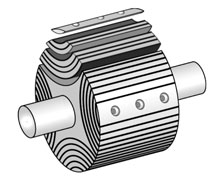
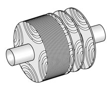
Working principle of synchronous reluctance motor
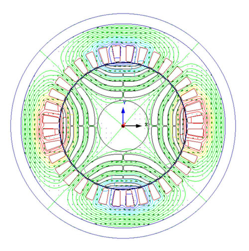
The alternating current passing through the stator windings creates a rotating magnetic field in the air gap of the electric motor. Torque is created when the rotor attempts to establish its most magnetically conductive axis (d-axis) with an applied field in order to minimize the reluctance (magnetic resistance) in the magnetic circuit. The amplitude of the torque is directly proportional to the difference between the direct Ld and quadrature Lq inductances. Therefore, the greater the difference, the greater the torque created.
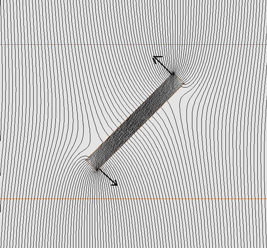
The main idea can be explained with the help of the figure below. The object "a" consisting of anisotropic material has a different conductivity along the d axis and the q axis, while the isotropic magnetic material of the object "b" has the same conductivity in all directions. The magnetic field that is applied to the anisotropic object "a" creates a torque if there is an angle between the d axis and the lines of the magnetic field. Obviously, if the d axis of the object "a" does not coincide with the lines of the magnetic field, the object will introduce distortions into the magnetic field. In this case, the direction of the distorted magnetic lines will coincide with the q axis of the object.
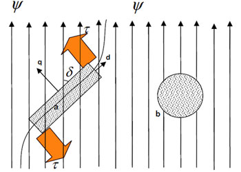
In a synchronous reluctance motor, a magnetic field is created by a sinusoidally distributed stator winding. The field rotates at synchronous speed and can be considered sinusoidal.
In such a situation, there will always be a torque aimed at reducing the whole system potential energy by reducing the field distortion along the q axis (δ→0). If the angle δ is kept constant, for example, by controlling the magnetic field, then the electromagnetic energy will be continuously converted into mechanical energy.
The stator current is responsible for magnetization and for creating a torque that attempts to reduce field distortion. The torque is controlled by controlling the current angle, that is, the angle between the current vector of the stator winding and the rotor d-axis in a rotating coordinate system.
Features of the synchronous reluctance motor
-
Advantages:
- Simple and robust rotor construction::
the rotor has a simple structure consisting of sheet electrical steel, without magnets and short-circuited winding. - Low heat:
since there are no currents in the rotor, it does not heat up during operation, increasing the service life of the electric motor. - No magnets:
the final price of the electric motor is reduced since rare earth metals are not used in production. In the absence of magnetic forces, the maintenance of the electric motor is simplified. - Low moment of inertia of the rotor::
since there is no winding and magnets on the rotor, the moment of inertia of the rotor is lower, which allows the electric motor to accelerate faster and save energy. - Speed control:
in view of the fact that synchronous reluctance motor for its operation requires a frequency converter, it is possible to control the speed of rotation of reluctance motor in a wide range of speeds.
-
Disadvantages:
- Frequency control:
to work requires a variable frequency drive. - Low power factor:
due to the fact that the magnetic flux is generated only by the reactive current. Solved by the use of a variable frequency drive with power correction.
