Permanent magnet synchronous motor
The main difference between a permanent magnet synchronous motor (PMSM) and an induction motor is in the rotor. Studies1 show that the PMSM has an efficiency of approximately 2% more than a highly efficient (IE3) induction electric motor, provided that the stator has the same design, and the same variable frequency drive is used for control. In this case, permanent magnet synchronous electric motors in comparison with other electric motors have the best performance: power/volume, torque/inertia, etc.
Permanent magnet synchronous motor constructions and types
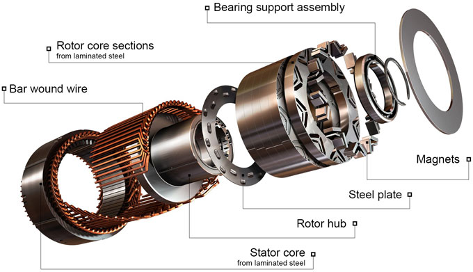
A permanent magnet synchronous motor, like any rotating electric motor, consists of a rotor and a stator. The stator is the fixed part. The rotor is the rotating part.
Typically, the rotor is located inside the stator of the electric motor, there are also structures with an external rotor - inside out electric motors.
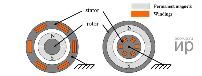
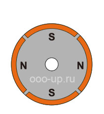
The rotor consists of permanent magnets. Materials with high coercive force are used as permanent magnets.
- According to the rotor design, synchronous motors are divided into:
- electric motors with salient pole rotor;
- electric motors with non-salient pole rotor.
An electric motor with non-salient pole rotor has an equal direct and quadrature inductances L d = Lq, whereas for an electric motor with salient pole rotor the quadrature inductance is not equal to the direct Lq ≠ Ld.
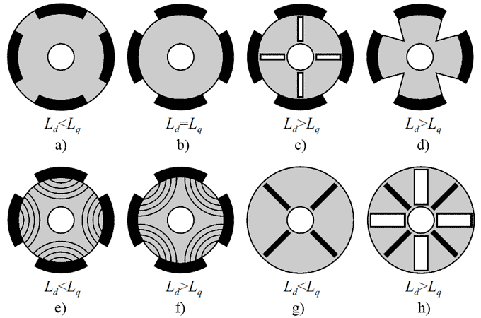
- Also, according to the design of the rotor, the PMSM are divided into:
- surface permanent magnet synchronous motor;
- interior permanent magnet synchronous motor.
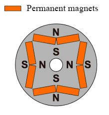
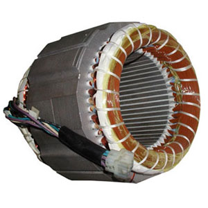
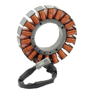
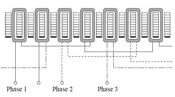
The stator consists of an outer frame and a core with windings. The most common design with two- and three-phase winding.
- Depending on the stator design, a permanent magnet synchronous motor can be:
- with distributed winding;
- with concentrated winding.
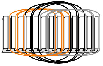
Distributed call such a winding, in which the number of slots per pole and phase Q = 2, 3, ...., k.
Concentrated called such a winding, in which the number of slots per pole and phase Q = 1. In this case, the slots are evenly spaced around the circumference of the stator. The two coils forming the winding can be connected both in series and in parallel. The main disadvantage of such windings is the impossibility of influencing on the form of the EMF curve [2].
- The form of the back EMF of the electric motor can be:
- trapezoidal;
- sinusoidal.
The form of the EMF curve in the conductor is determined by the distribution curve of the magnetic induction in the gap around the stator circumference.
It is known that the magnetic induction in the gap under the salient pole of the rotor has a trapezoidal shape. The EMF induced in the conductor has the same form. If it is necessary to create a sinusoidal EMF, then the pole tips are given such a shape that the induction distribution curve would be close to sinusoidal. This is facilitated by the bevels of the pole tips of the rotor [2].
Working principle of a synchronous motor
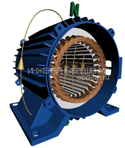
The principle of operation of a synchronous motor is based on the interaction of the rotating magnetic field of the stator and the constant magnetic field of the rotor. The concept of the rotating magnetic field of the stator of a synchronous motor is the same as that of a three-phase induction motor.
The principle of operation of a synchronous motor is based on the interaction of the rotating magnetic field of the stator and the constant magnetic field of the rotor.
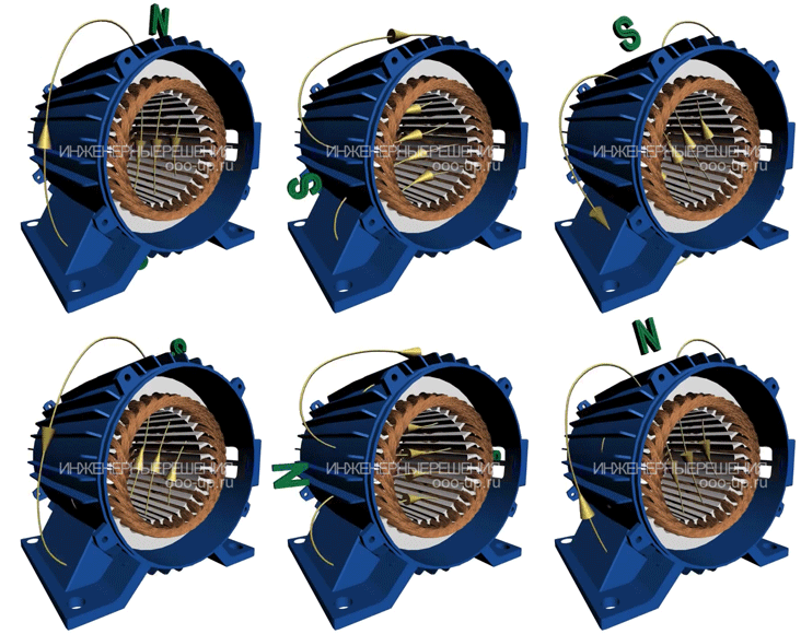
The magnetic field of the rotor, interacting with the synchronous alternating current of the stator windings, according to the Ampere's Law, creates torque, forcing the rotor to rotate (more).
Permanent magnets located on the rotor of the PMSM create a constant magnetic field. At a synchronous speed of rotation of the rotor with the stator field, the rotor poles interlock with the rotating magnetic field of the stator. In this regard, the PMSM cannot start itself when it is connected directly to the three-phase current network (current frequency in the power grid 50Hz).
Control of PMSM
A permanent magnet synchronous motor requires a control system, for example, a variable frequency drive or a servo drive. There are a large number of control techniques implemented control systems. The choice of the optimal control method mainly depends on the task that is put in front of the electric drive. The main methods for controlling a permanent magnet synchronous motor are shown in the table below.
| Control | Advantages | Disadvantages | |||
|---|---|---|---|---|---|
| Sinusoidal | Scalar | Simple control scheme | Control is not optimal, not suitable for tasks where the variable load, loss of control is possible | ||
| Vector | Field oriented control | With position sensor | Smooth and precise setting of the rotor position and motor rotation speed, large control range | Requires rotor position sensor and powerful microcontroller inside the control system | |
| Without position sensor | No rotor position sensor required. Smooth and precise setting of the rotor position and motor rotation speed, large control range, but less than with position sensor | Sensorless field oriented control over full speed range is possible only for PMSM with salient pole rotor, a powerful control system is required | |||
| Direct torque control | Simple control circuit, good dynamic performance, wide control range, no rotor position sensor required | High torque and current ripple | |||
| Trapezoidal | Open loop | Simple control scheme | Control is not optimal, not suitable for tasks where the variable load, loss of control is possible | ||
| Closed loop | With position sensor (Hall sensors) | Simple control scheme | Hall sensors required. There are torque ripples. It is intended for control of PMSM with trapezoidal back EMF, when controlling PMSM with sinusoidal back EMF, the average torque is lower by 5%. | ||
| Without sensor | More powerful control system required | Not suitable for low speed operation. There are torque ripples. It is intended for control of PMSM with trapezoidal back EMF, when controlling PMSM with sinusoidal back EMF, the average torque is lower by 5%. | |||
To solve simple tasks is usually used trapezoidal control with Hall sensors (for example, computer fans). To solve problems that require maximum performance from the electric drive, field-oriented control is usually selected.
Trapezoidal control
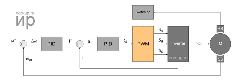
One of the simplest methods of control of a permanent magnet synchronous motor is - trapezoidal control. Trapezoidal control is used to control the PMSM with trapezoidal back EMF. At the same time, this method also allows you to control the PMSM with a sinusoidal back EMF, but then the average torque of the electric drive will be lower by 5%, and the torque ripples will be 14% of the maximum value. There is a trapezoidal control without feedback and with feedback by the rotor position.
The open loop control (without feedback) is not optimal and may lead to the release of the PMSM out of synchronism, i.e. to loss of controllability.
- The closed loop control can be divided into:
- trapezoidal control by position sensor (usually by Hall sensors);
- trapezoidal control without sensor (sensorless trapezoidal control).
As a rotor position sensor for three-phase trapezoidal control, three Hall sensors built into an electric motor are commonly used, which allow determining the angle with an accuracy of ± 30 degrees. With this control, the stator current vector takes only six positions for one electric period, as a result of which there is ripple torque at the output.
Field oriented control
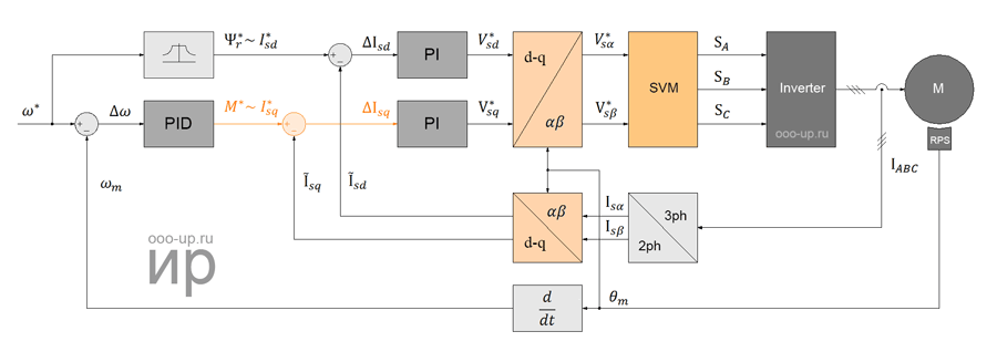
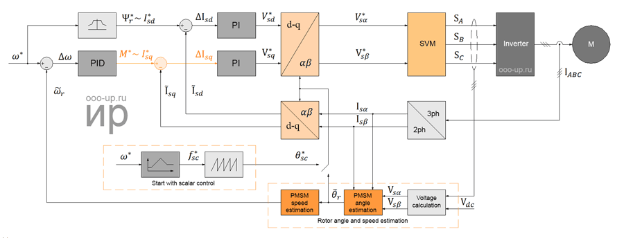
Field-oriented control (FOC) allows you to smoothly, accurately and independently control the speed and torque of a brushless motor. For the operation of the field oriented control algorithm, it is necessary to know the position of the rotor of the brushless motor.
- There are two ways to determine the rotor position:
- by the position sensor;
- sensorless - by calculating the angle by the real-time control system based on the information available.
PMSM field oriented control by position sensor
- The following types of sensors are used as angle sensors:
- inductive: resolver, inductosyn, etc .;
- optical;
- magnetic: magnetoresistive sensors.
Field-oriented control of PMSM without a position sensor
Since the 1970s sensorless vector control methods for brushless AC motors began to be developed, thanks to the rapid development of microprocessors. The first sensorless methods for estimating the angle were based on the property of the electric motor to generate back EMF during rotation. The motor back EMF contains information about the position of the rotor, therefore, by calculating the value of the back EMF in the stationary coordinate system, you can calculate the position of the rotor. But when the rotor is not rotating, the back EMF is absent, and at low speed the back EMF has a small amplitude, which is difficult to distinguish from noise, therefore this method is not suitable for determining the position of the motor rotor at low speed.
- There are two common techniques for sensorless start PMSM:
- start by the scalar method - start on a predetermined characteristic of voltage dependence to frequency. But scalar control severely limits the capabilities of the control system and the parameters of the electric drive as a whole;
- high frequency signal injection method – works only with the salient pole PMSM.
At present, sensorless field-oriented control of PMSM in the full speed range is possible only for motors with salient pole rotor.
