Hysteresis-reluctance synchronous motor
A self-starting synchronous hysteresis-reluctance motor with a reduction gear was invented in 1916 by Henry Ellis Warren. These electric motors were made low-power and were widely used until recently to drive program mechanisms and for timing applications (electric clocks, time switches, graphical recording instruments, and stroboscope devices, etc.).
Construction of a synchronous hysteresis-reluctance motor
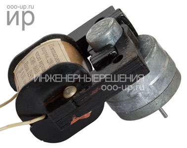
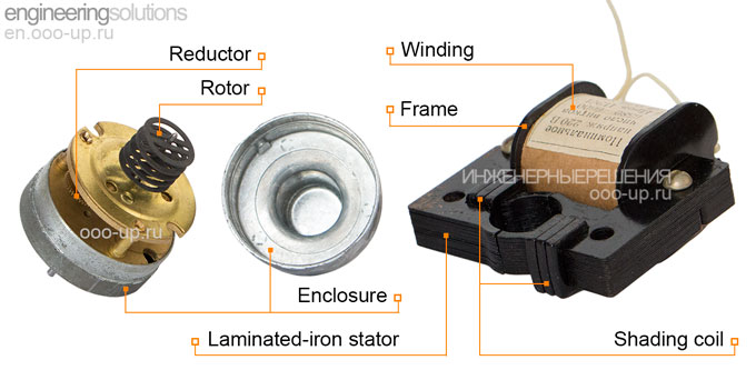
Synchronous hysteresis-reluctance motor as well as any electric motor, consists of a rotor and a stator. The stator is a stationary part, the rotor is a rotating part.
The stator of a single-phase hysteresis-reluctance electric motor is similar to the stator of a single-phase induction electric motor with shaded pole and has a laminated core with two salient poles. To simplify the installation of single-phase winding, the stator core is collapsible, consisting of two halves. The poles of the stator core end with pole tips. Each pole is divided into two equal sections by a longitudinal groove. One of the section of each pole has short-circuited copper turns, providing a rotating magnetic field in a single-phase motor [2]. Shaded pole motors are irreversible. The rotor always rotates only in one direction from the unshaded section of the stator pole to the shaded.
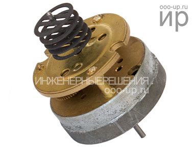
The rotor includes two or more disks 0.4 mm thick of hardened hard magnetic steel. To create a hysteresis torque, a steel with a large residual magnetization is selected. The discs have the form of rings with bridges. The magnetic reluctance of the rotor in the direction of the bridges is less, and therefore the direct axis xd and quadrature axis xq magnetic reactances are not equal, which creates also a reluctance torque. An annular rim on the rotor discs provides eddy current torque and hysteresis torque. The rotor is mounted on the shaft using slots in the bridges of the discs. The motor shaft is connected to a reducer that lowers the rotational speed and increases the torque. The rotor with a reducer is placed in a sealed enclosure made of non-magnetic metal.
Working principle of a synchronous hysteresis-reluctance motor
In a hysteresis-reluctance motor three electromagnetic torque is created. At motor start-up, on the rotor is acted hysteresis torque and eddy current torque. The magnetic hysteresis of the steel rotor reduces the efficiency of the motor but significantly increases the starting torque. After start-up, the rotor is pulled into synchronism and rotates at a constant synchronous speed under the action of the hysteresis and reluctance torque.
Advantages and disadvantages
Warren's synchronous hysteresis-reluctance motors with relatively large overall dimensions and mass have low energy indices (efficiency and cosφ). However, they were widely used in automatic devices due to the simplicity of design, manufacturability and the ability to work from single-phase power.


