Brushed DC electric motor
Construction of brushed DC electric motor
Rotor is rotating part of the electric machine.
Stator is a fixed part of the motor.
Inductor (excitation system) is part of the DC commutator machine or synchronous machine, creating magnetic flux for the formation of the torque. The inductor includes either permanent magnets or a field winding. The inductor can be part of both the rotor and the stator. In the motor shown in fig. 1, the excitation system consists of two permanent magnets and is part of the stator.
Armature is a part of a DC commutator machine or a synchronous machine in which an electromotive force is induced and a load current flows [2]. As the armature can act as a rotor and stator. In the motor shown in fig. 1, the rotor is an armature.
Brushes is a part of the electrical circuit through which the electric current is transmitted from the power source to the armature. Brushes are made from graphite or other materials. The DC motor contains one pair of brushes or more. One of the two brushes is connected to the positive and the other to the negative terminal of the power supply.
Commutator is a part of the motor in contact with the brushes. With the help of brushes and a commutator, the electric current is distributed across the coils of the armature winding [1].
Types of brushed DC motors
According to the stator construction, the brushed motor can be with permanent magnets and with wound stator.
Permanent magnet DC motor
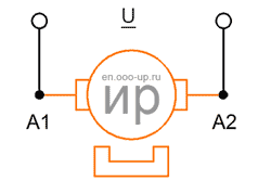
Permanent magnet DC motor (PMDC motor) is the most common among the brushed DC motor. The inductor of this motor includes permanent magnets that create a magnetic field of the stator. Permanent magnet DC motors are usually used in tasks that do not require high power. PMDC motors are cheaper in production than wound field DC motors. At the same time, the torque of the PMDC motor is limited by the field of permanent magnets of the stator. The PMDC motor reacts very quickly to voltage changes. Thanks to the constant field of the stator, it is easy to control the speed of the motor. The disadvantage of a PM DC motor is that over time the magnets lose their magnetic properties, as a result of which the stator field decreases and the motor performance decreases.
- Advantage:
- best price/quality ratio
- high torque at low speed
- fast voltage response
- Disadvantage:
- permanent magnets over time, as well as under the influence of high temperatures lose their magnetic properties
Wound field DC motor
- According to the wiring diagram of the stator winding, wound field DC motors are divided into:
- separately excited DC motor
- shunt wound DC motor
- series wound DC motor
- compound wound DC motor
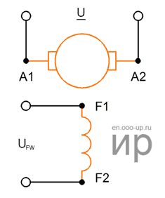
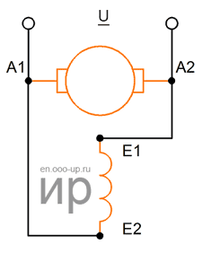
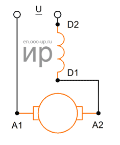
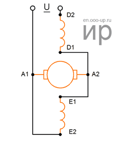
Separately excited and shunt wound motors
In separately excited electric motors, the field winding is not electrically connected to the armature winding (figure above). Usually, the excitation voltage UFW differs from the voltage in the armature circuit U. If the voltages are equal, then the field winding is connected in parallel with the armature winding. The use in the electric drive separately excited or shunt wound motor is determined by the electric drive scheme. Properties (characteristics) of these motors are the same [3].
In shunt wound brushed DC motors, the currents of the field winding (inductor) and the armature are independent of each other, and the total motor current is equal to the sum of the field winding current and the armature current. During normal operation, increasing the supply voltage increases the total current of the motor, which leads to an increase in the stator and rotor fields. With an increase in the total motor current, the speed also increases, and the torque decreases. When the motor load increased, the armature current increases, with the result that the armature field increases. As the armature current increases, the inductor (field winding) current decreases, resulting in a decrease in the inductor field, which leads to a decrease in motor speed and an increase in torque.
- Advantage:
- almost constant torque at low speed
- good adjusting properties
- no loss of magnetism over time (since there are no permanent magnets)
- Disadvantage:
- more expensive than PMDC motor
- the motor goes out of control if the inductor current drops to zero
Shunt-wound DC motor has the torque/speed characteristic with decreasing torque at high speeds and high, but more constant torque at low speeds. The current in the inductor winding and the armature does not depend on each other, thus, the total current of the electric motor is equal to the sum of the currents of the inductor and the armature. As a result, this type of motor has excellent speed control characteristics. Shunt-wound brushed DC motor is commonly used in applications that require a power of more than 3 kW, in particular in automotive applications and industry. In comparison with PMDC motor, the shunt wound DC motor does not lose its magnetic properties with time and is more reliable. The disadvantages of the shunt wound brushed DC motor is higher cost and the possibility of the motor runaway if the inductor current decreases to zero, which in turn can lead to motor failure [5].
Series wound DC motor
In series wound brushed DC motors, the field winding is connected in series with the armature winding, and the excitation current is equal to the armature current (Ie = Ia), which gives the motors special properties. Under small loads, when the armature current is less than the rated current (Ia < Irat) and the magnetic system of the motor is not saturated (Ф ~ Iа), the electromagnetic torque is proportional to the square of the current in the armature winding:
 ,
,
- where M is the motor torque, N∙m,
- сМ is a constant coefficient determined by the design parameters of the motor,,
- Ф is main magnetic flux, Wb,
- Ia is armature current, A.
With load increasing, the magnetic system of the motor is saturated and the proportionality between the current Ia and the magnetic flux Ф is disturbed. With significant saturation, the magnetic flux Ф with increasing Ia practically does not increase. The graph of the dependence M=f(Ia) in the initial part (when the magnetic system is not saturated) has the shape of a parabola, then, when saturated, deviates from the parabola and in the region of large loads turns into a straight line [3].
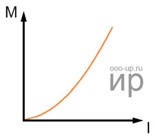
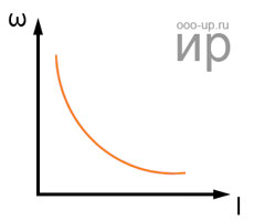
The ability of series wound DC motors to develop a large electromagnetic torque provides them with good starting properties.
- Advantage:
- high torque at low speed
- no loss of magnetism over time
- Disadvantage:
- low torque at high speed
- more expensive than PMDC motor
- poor speed control due to the series connection of the armature and inductor windings
- the motor goes out of control if the inductor current drops to zero
Series wound brushed DC motor has a high torque at low speed and develops high speed with no load. This electric motor is ideal for devices that need to develop a high torque (cranes and winches), as the current of the stator and the rotor increases under load. Unlike PMDC motors and shunt wound brushed DC motors, the series wound DC motors does not have the exact characteristics of speed control, and in case of a short circuit of the field winding it can become uncontrollable.
Compound wound DC motor
Compound wound brushed DC motor has two field windings, one of them is connected in parallel with the armature winding, and the second is connected in series. The ratio between the magnetizing forces of the windings can be different, but usually one of the windings creates a large magnetizing force and this winding is called main, the second winding is called auxiliary. If the windings are connected such that the series field aids the shunt field, then the motor is called Cumulative compound brushed DC motor. On the other hand, if the windings are connected such that the two fields oppose each other, then the motor is called the Differential compoud brushed DC motor. The speed characteristics of cumulative compound brushed DC motor are located between the speed characteristics of shunt wound and series wound DC motors. Opposite connection of the windings (differential compounding) is used when it is necessary to obtain a constant rotational speed or an increase in the rotational speed with increasing load. Thus, the performance characteristics of a compound wound DC motor is close to those of a shunt or series wound brushed DC motor, depending on which field winding plays the main role [4].
- Advantage:
- good speed control
- high torque at low speed
- motor runaway less likely
- no loss of magnetism over time
- Disadvantage:
- more expensive than other brushed DC motors
Compound brushed DC motors has the performance characteristics of shunt and series wound brushed DC motors. It has a high torque at low speed, as well as a series wound brushed DC motor and good speed control, like, a shunt wound brushed DC motor. Compound wound brushed DC motor runaway is less likely, because the shunt current should decrease to zero, and the serial field winding should be short-circuited.
Performance characteristics of brushed DC motors
The performance properties of brushed DC motors are determined by their operating, electromechanical and mechanical characteristics, as well as their adjustment properties.
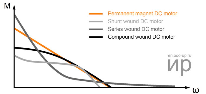
The main parameters of the brushed DC motor
Torque constant
For a brushed DC motor, the torque constant is determined by the formula:
 ,
,
- where Z is total number of conductors,
- Ф is magnetic flux, Wb [1]
- T.Kenjo, S.Nagamori. Permanent Magnet and Brushless DC Motors. - Moscow: 1989.
- GOST 27471-87 Rotating electrical machines. Terms and definitions.
- M.M.Katsman. Electrical machines and electric drive of automatic devices: A textbook for electrical engineering technical schools. - Moscow: 1987.
- L.M.Piotrovsky. Electric machines. A textbook for students of electrical engineering and energy technical schools. - Leningrad: 1972.
- Microchip. Brushed DC motor basics.